
Jake Kavanagh gets expert advice about the best place to fit antennas, the pros and cons of splitters, plus emergency options
Sometimes there is only room for one VHF antenna to be mounted at height, but what if you want to fit AIS as well? Do you use a splitter, or have a second antenna lower down?
“There is no substitute for one antenna being connected directly to one radio system via one feed line, preferably a high-quality coaxial cable,” says Terry Slack, former senior lecturer in marine communications at Southampton Solent University. “However, it sometimes becomes necessary to share an antenna with more than one radio system. “The point to remember here, though, is that there’ll always be a degree of loss in the system as soon as you introduce another item. The degree of loss is extremely important, especially when considering the received signal strength at the radio. This loss is not so critical, however, when it comes to transmissions.”
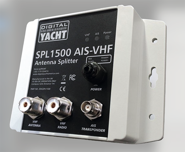
A typical antenna splitter. Credit: Digital Yacht
Other systems that may share the same antenna include AM/FM radio for entertainment, and the Automatic Identification System (AIS) for safety. AIS was devised in the early 1990s and eventually came into service in 2002. A huge boost to general maritime safety, it allowed vessels to recognise each other electronically. Data sent from sensors on board one vessel could be seen as graphics on a display on another, relaying basic information such as the vessel’s name, type, speed, course, bearing and range.
However, the system needed to use two international marine VHF frequencies, both set aside for this task, and remained limited in range by ‘line of sight’. Meanwhile, the AIS-equipped vessel still needed to use its VHF radio for voice calls, and a respectable distance of at least 2m was needed between the VHF radio antenna and its AIS counterpart.
This is because the radio can transmit at 25W, but the AIS only uses 2W; this means that if the radio antenna is too close, the AIS receiver can be damaged
by the energy radiated from a 25W radio transmission.
For commercial ships over 300 gross register tonnage (GRT), AIS became mandatory in 2002, and separating the two antennae wasn’t a problem. However, in 2006, smaller and less complex AIS transponders known as ‘Class B’ became available for vessels under the mandatory tonnage, making AIS both affordable and desirable for the leisure sector.
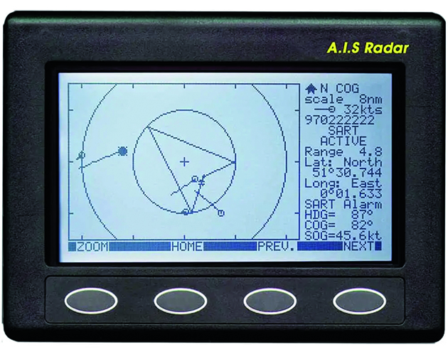
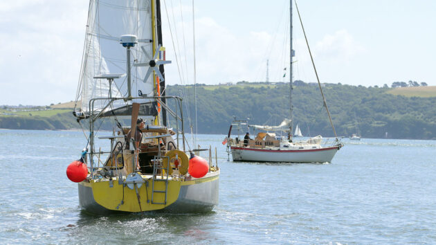
The Automatic Identification System (AIS) shows the relative positions of similarly equipped vessels, their course, speed and type, and their Maritime Mobile Service Identification (MMSI) number for direct contact. No more trying to read names through binoculars. This is the budget NASA Radar version, retailing at just under £300. Credit: Nasa
Boat owners soon began to recognise AIS as a useful navigation aid, especially for those without radar, but who could still ‘see’ the relative positions of AIS-equipped vessels on a screen. Even more useful was that they knew who they were and what their call sign was, so the vessels were easy to call up if there was some doubt about intentions.
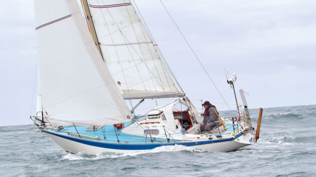
The owners of smaller boats, however, struggled to find a way to have both antennas as high as possible for the best line-of-sight range, but without the signals interfering with each other. Some fitted the AIS onto the stern rail instead, leaving the VHF antenna at the top of the mast.
The big issue with the AIS being so low was that its 2W transmission range of 7-8 miles was effectively halved, or even completely compromised in a seaway, so it became very inefficient.
Motorboaters with a radar arch could sometimes mount an antenna on each side, provided there was more than 2m of beam available between them.
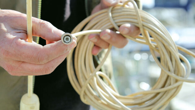
Losses can be caused by adding additional equipment to the coaxial cable or using low-quality cable and connectors. Don’t compromise on the cost, and only break the cable if necessary. Credit: Jake Kavanagh
“All feed lines (coaxial cable) experience some loss,” Terry Slack explains. “This happens even if the radio is connected directly to the antenna via a length of coax. The quality of the coaxial cable directly relates to the level of loss over a given distance. If any item like a splitter, VSWR Bridge (Voltage Standing Wave Ratio impedance tester) or filter is added to this antenna system, then an additional loss will exist. How much of a loss from the extra item will vary depending on its build quality.”
Slack states that if your transmitter outputs 25W into a low-quality coaxial cable with an equally low-quality splitter in the circuit, then the overall loss could be significant. However, this primarily becomes a problem when receiving due to the very small voltages involved.
“Even if the transmission loss in the system reduces the output power from 25W to 12W at the antenna, the overall effect on other stations would be in the order of around 3dB (decibels),” Slack said. “In other words, the result would be to reduce a signal level of say 5 at another receiving station to a signal level of 4.5. So, although the system loss is significant, it won’t have much of an impact on radio communication.”
However, when it comes to the receiver, the problem with poor components is more of an issue.
“Here we are looking at received signal levels in values of microvolts (V),” Slack said. “Marine radios are specified as having something like 0.25V for 12dB SINAD. (Radio SINAD is Signal-to-Noise And Distortion and measures a receiver’s sensitivity. The higher the SINAD, the better the received signal, with 12dB being the standard threshold for usable and intelligible radio comms). This basically means that you would be receiving a good signal level at the radio’s loudspeaker if the signal at the antenna was 0.25V. The idea, of course, is to transfer as much of that 0.25V to the radio with as little loss in the coax feed line as possible. So, adding anything to this system’s feed line is not the best policy. Best practice is to have a separate antenna, coax and receiver (AIS receiver), but this is not always possible.”
As a former BT engineer, Slack speaks from his long experience with system development in the UK’s coastal radio station network.
“We were running at least four full duplex VHF channels at each station, and it was interesting work trying to stop them from interfering with each other,” he said. “We were always successful, as we found the answer was sensible positioning of antennas and the use of high-quality coaxial cable. These were combined with well-engineered and tuneable notch filters.” (A notch filter suppresses a very narrow range of radio frequencies while allowing others to pass through, but with little or no attenuation.)
A solution for making the best use of one well-positioned antenna is to fit a splitter, a device that allows the antenna to perform both radio and AIS tasks. Splitters come in two forms, active (powered for amplification) and passive (unpowered). Both split the signal between the two receivers, but this sometimes comes at a cost to reception.
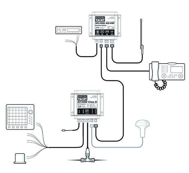
This diagram from Digital Yacht explains how a splitter can be inserted into the system. While one of the more costly on the market, this powered unit allows much greater functionality for the system and features ‘zero loss’ technology. Credit: Digital Yacht
A major international manufacturer of splitters is Digital Yacht, with offices in the UK and the US. “Splitters have been around for some time,” explained CEO Nick Heyes. “Prior to AIS, splitters would be used to allow an AM/FM radio to share the VHF antenna. When the first AIS receivers were launched, many yacht owners used a splitter so the receiver and the VHF could share the same antenna.
“Although this made installation quite easy, the traditional splitter was often a crude device and many sailors subsequently found their VHF reception range was significantly reduced. This was not ideal for those who’d installed a high-quality VHF antenna at the top of the mast to get maximum VHF range.”
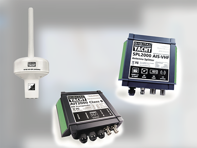
Splitters can be combined with equipment from the same manufacturer, including an antenna specially tuned to the AIS frequency, to ensure the best signal strength. Credit: Digital Yacht
For lecturer Terry Slack, the issue lies in the physics of frequencies. “The first thing to consider is that the VHF Marine Band is from 156MHz to approximately 174MHz,” he said. “Included within this spectrum are all marine communications channels and the AIS channels at 161.975MHz (AIS 1 Ch87B) and 162.025MHz (AIS 2 Ch88B). So, successful use of a splitter will need a device that will allow all VHF communications channels to be fed through to the VHF receiver – and the AIS receiver – with minimum loss. The ideal situation is to ensure that the filtering within the splitter maintains a balance of 50 ohms (Ω) at the input from the antenna. It must also maintain the 50Ω balance at the output feeds to our VHF receiver and the AIS receiver.”
“Unlike the traditional splitters, our latest SPL2000 model uses a new ‘Zero Loss’ technology that boosts the received signals prior to splitting them,” Heyes explained. “This results in no loss of reception on either the AIS or VHF. Therefore, sailors can have a simple and easy-to-install splitter with no reduction in performance.”
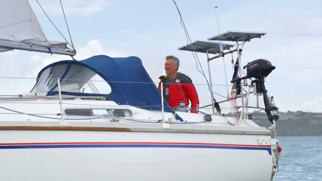
Smaller yachts usually use the stern rail. Here you can see the whip attached between the solar panels, and zip tied to stop it ‘whipping.’ The tube above it is an Echomax radar enhancer. Credit: Jake Kavanagh
Heyes says that installation simply involves unplugging the VHF antenna from the back of the radio. You then connect it to the SPL2000 along with the supplied cables that go to the radio and AIS. The splitter works with any Class B transponder, he says, not just those made by Digital Yacht.
Heyes also warns about the risk of a low-quality unit being introduced into the system, a component usually identified by a tempting price.
“It’s important to note that a Class B Transponder needs a special type of splitter,” he advises. “This has two intelligent switches inside that can detect when either the VHF or AIS is transmitting. Then, in less than a few milliseconds, it can disconnect the other device while the transmission takes place. “Traditional lower cost (£50-£70) splitters only have one simple switch, and you should never use one with a Class B transponder.”
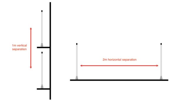
VHF and AIS antenna separation: Due to the different output powers of the AIS system (Class B transmits at 2W, class B+ at 5W) the antenna needs to be kept apart from the more energy-intensive 25W VHF radio transmitter. Credit: Digital Yacht
Slack concurs that issues can arise from a cheap splitter when it comes to fast reactions and preventing radio signal leakage.
“If the splitter is not designed well, it’s possible that some of the transmitted radio frequency (RF) could leak into the AIS receiver,” he said. “This would have the effect of blocking any AIS signals being received and quite possibly, the RF could actually damage the AIS receiver input circuits.”
A high-quality splitter has safeguards built in to prevent this, Slack said. “The ideal solution is to build filters that are so tight that they totally reject any RF signals (even very strong signals) from the VHF transmitter,” he explained. “This protects the aerial input circuits of the AIS receiver. The difference in frequency from a typical marine VHF transmitting frequency and the AIS frequencies is not very great and so the engineering involved in designing these tight filters must be very exact.
“Alternatively, a splitter might simply disconnect the aerial input to the AIS receiver while the marine VHF is transmitting. This would have the effect of protecting the AIS receiver from damage. Once the transmitter had stopped transmitting, the AIS protection circuit would be disconnected so the AIS receiver could once again receive AIS signals.”
Best VHF AIS antenna location
The best scenario, then, is to have a VHF radio antenna mounted as high as possible and fitted with a high-quality coaxial cable with no additions in between. A second dedicated AIS antenna also needs to be mounted as high as possible, but where?
Larger motorboats usually have enough space on the radar arch to separate the two antennae, as seen here on this 45-footer. The larger main VHF antenna is on the side; the smaller AIS is on the stainless-steel bridge. Credit: Jake Kavanagh
“Digital Yacht has traditionally recommended the use of a dedicated AIS/VHF antenna for connection to their AIS units,” Heyes confirms, adding that these are often specifically ‘tuned’ to the AIS frequencies for greater sensitivity.
“Ideally this would be mounted as high as possible, such as on an antenna bracket at the stern of the boat or, space permitting, on the spreaders. Failing this, the dedicated antenna can be mounted at deck level on the stern rail. This will still provide reasonable reception of the large ship Class A transponders – typically
10-15 miles.”
Many sailors have added a ‘goal post’ gantry on the stern, allowing the higher positioning of AIS and back-up VHF aerials. Credit: Jake Kavanagh
Ketches and schooners can use each mast to house a separate antenna, with either the VHF or the AIS on the tallest mast, depending on the boat owner’s priorities.
Bluewater sailors, for example, may want to keep an AIS perimeter watch active at all times, so an alarm sounds when any vessel breaches a pre-set boundary. It makes sense to give the AIS the best range possible, so the tallest mast would be chosen. Heyes suggests that boat owners must weigh up the time and cost implications of installing a dedicated VHF/AIS antenna versus the cost of a splitter.
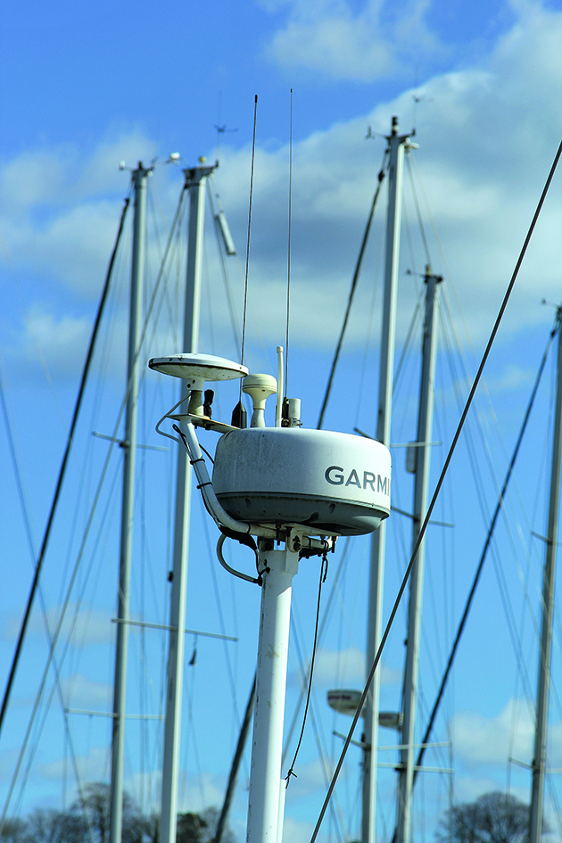
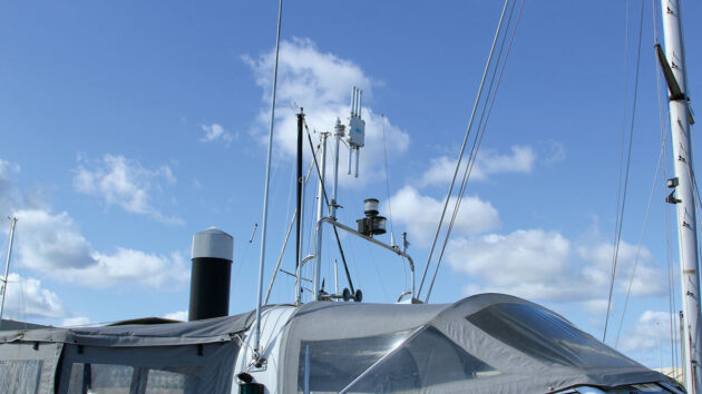
Another solution is to mount the antenna along with other receivers, such as the GPS, on a dedicated proprietary radar mast behind the cockpit. Ideally, the radar scanner should be well above head height in operation. Credit: Jake Kavanagh
“Our GV30 combo GPS/AIS antenna helps to make installation easier,” he says. “It achieves this by having just the one antenna to find a location for. Slim FME-type (threaded 50Ω coaxial) connectors on the two cables also make routing them through the boat easier.
“On smaller boats, the GV30 is an ideal antenna for any Class B transponder. It is becoming a popular option with our AIT2000 transponders, too.”
Conclusions
So, to split or not to split? These are our top takeaways from the expert feedback:
- If possible, use two separate antennae, one for AIS and the other for VHF.
- Select an AIS antenna specifically designed and ‘tuned’ for that task.
- Make sure the two antennae are at least 2m apart horizontally, or 1m apart vertically
- Minimise the interruptions/joints to the coaxial cable for each.
- Use only high-quality coaxial cable, remembering the price will reflect this.
- Fit a splitter if you don’t have anywhere suitable to mount the AIS without greatly compromising its functionality, or if you want the maximum possible transmit range.
- Choose a good-quality splitter from a reputable brand.
- Remember that low-cost splitters can often perform poorly by introducing an unacceptable loss into the system.
Emergency VHF Antenna
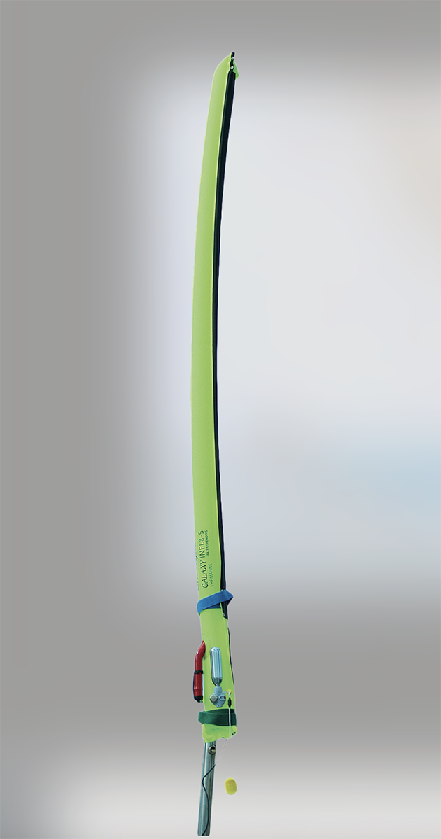
An emergency VHF antenna will allow you to continue transmitting even if your antenna is damaged, or lost in a dismasting. Credit: Shakespeare Marine
Masthead antenna can fail for several reasons, the most catastrophic being a dismasting. However, an emergency VHF can be rigged by either using the separate AIS antenna or attaching a spare aerial to a pole – a boat hook or tender paddle will serve – and then plugging the coax plug into the set.
Range will be limited by the lack of height, but may be enough to reach a nearby vessel for a Mayday or Pan-Pan (urgency) relay.
This hot swap for the AIS antenna is endorsed by Digital Yacht’s Nick Heyes. “If you keep the necessary adaptor,” he says, “then in the event of your main VHF antenna failing, you can quickly unplug the AIS antenna and connect it to the VHF radio instead.”

What is AIS Class B+ and do I need it for my boat?
I ’d been thinking about buying an AIS transceiver for my Merry Fisher 855 for some time. I use my…

SSB radio antenna: How can I install one on my boat? Our expert answers
Q: I recently bought a NASA Target HF3 SSB radio antenna receiver. The manual that came with it is OK…

How to test an old VHF antenna and cable
A reader's question about testing a VHF antenna and coaxial cable answered by one of PBO's experts
Satellite internet for under £400, but how good is the Starlink Mini for staying in contact offshore?
The Starlink Mini is changing how offshore sailors communicate, offering high-speed internet for a surprisingly small hardware cost, but how…
Want to read more articles like Where to fit a VHF AIS antenna?

A subscription to Practical Boat Owner magazine costs around 40% less than the cover price.
Print and digital editions are available through Magazines Direct – where you can also find the latest deals.
PBO is packed with information to help you get the most from boat ownership – whether sail or power.
-
-
-
- Take your DIY skills to the next level with trusted advice on boat maintenance and repairs
- Impartial, in-depth gear reviews
- Practical cruising tips for making the most of your time afloat
-
-
Follow us on Facebook, Instagram, TikTok and X