
Charles Morland explains how he fitted a bilge pump and timer switch system to his Fairways Freeward motor-sailer
If, like me, you have a boat with a traditional stuffing box that needs to be adjusted so it drips slightly to ensure adequate lubrication of the gland packing, then installing a bilge pump helps ensure peace of mind. Unfortunately, automatic electric bilge pumps are not always as reliable as you’d wish such a vital item to be. Most bilge pumps use a centrifugal impeller to do the actual pumping and, just like the impeller in an engine raw water cooling circuit, they’re easily damaged if they run dry.
The automatic switches used to control them are usually based on a float and micro switch: a rather delicate arrangement to have in a hostile environment such as the bilge. In addition it’s not unknown for the float switch to either jam open, which means no pumping action, or closed – which leads to a burned-out impeller. Finally, there’s the problem of ‘pump hunting’ where the float rises, switches on the pump, the water level drops marginally and the pump switches off, only to start again shortly afterwards when the water level rises fractionally. In a worst-case scenario this can happen simply because of wave action or the wash from a passing boat. Too much ‘hunting’ can wreak havoc with switch contacts. When carrying out a refit on my Fairways Freeward motor-sailer Hedda I was determined to eliminate these problems.
Preparing to install a bilge pump
My starting point was my Whale Gulper pump. It works on the same principle as a manual bilge pump that uses a diaphragm and flap valves, with the Gulper’s diaphragm being actuated by a coil and solenoid instead of a handle. The beauty of these pumps is that they can run dry without damage and are much more tolerant of any small pieces of debris which manage to get past the suction hose filter.
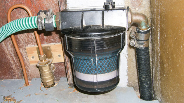
Install a bilge pump: Wavestream filter with oleophilic element catches spilt oil and diesel from the bilge before it is pumped overboard. Credit: Charles Morland
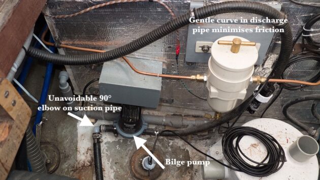
I mounted the pump low down in the engine compartment to minimise the lift required but high enough for the unit itself to be well clear of any water that found its way into the bilge in the normal run of things. A small cover was provided to protect the terminals for the power supply, and I fitted a strum box with non-return foot valve as well as a fine-mesh filter in the suction line. Ideally you should use as few junctions and connectors as possible in pump lines as these increase the friction and thus reduce the flow. Because of limited mounting options I unfortunately had to include a couple of right-angled connectors, but at least managed to achieve the remainder of the run for the suction and discharge lines using nothing more than gentle curves in the hose. This was important because I also installed a Wavestream filter with an oleophilic element. This filter traps bilge water hydrocarbons for a cleaner discharge into the environment, but introduces significant resistance into the discharge line.
Bilge pump actuation
The next question was how to trigger the pump. I decided that a solid-state switch would be the best option and remembered an article on how to make one in PBO (I’d cut out and kept the page). The design was based on the fact that air is a good insulator and water a good conductor. It consisted of a couple of stainless steel bolts to act as probes, held 25mm or so apart by being fastened through two holes in the top of a plastic cap from an aerosol can. A simple transistor-based circuit encapsulated in resin inside the cap monitors the resistance across the probes and provides an output to a switching relay that actuates the pump.
So, modifying the instructions slightly to suit my application, I made a switch and secured it with a length of stainless steel strip screwed to a transverse bearer suspended at an appropriate height over the bilge sump. While the probes were above the set water height no current could flow between them. When the water level rose and covered them current flowed and the encapsulated circuit became live.
Timer required
On its own the switch would not get over the problem of ‘pump hunting’. What was needed was some sort of timer which, once triggered by the sensor, would keep the pump running for a reasonable length of time in order to clear the bilge. After a great deal of scouring the internet I came across Cheshire-based firm PoleVolt, who could supply a combined relay and timer which had a delay adjustable between 0.5 seconds and 6 hours. Even better, it was the same size as a standard automotive relay and would therefore fit into a standard relay holder.
The switching terminals were rated at 10A compared with the pump manufacturer’s recommendation of an 8A fuse for the pump wiring, so in theory the timer relay would safely handle the pump’s operating current. However, as a timer relay is £30 plus postage, whereas a standard Lucas on/off relay is only a couple of pounds from any auto electrical outlet, I decided to use the timer relay output to trigger a standard on/off relay which then handled the current draw from the pump.
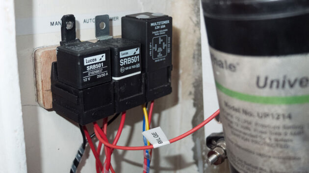
How to install a bilge pump: Plug-in relays and timer switch are mounted high and dry inside a wheelhouse locker. Credit: Charles Morland
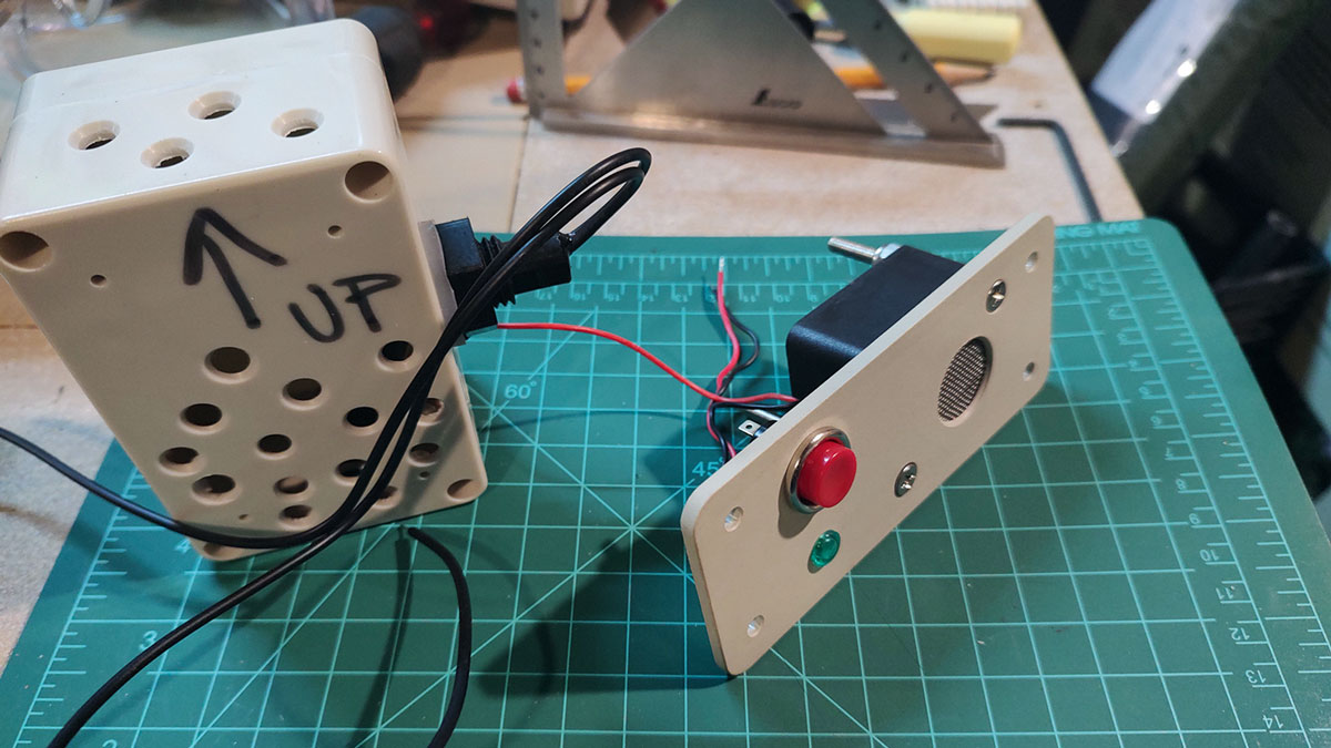
There are two small round plastic covers on the top of the timer relay. Removing the right-hand one reveals a small cross-headed screw marked with an arrowhead set in the centre of a white plastic disc numbered 1 to 10. These denote the various timing delay ranges available. I used option 7 which gave an adjustable delay of between 0.5 and 10 minutes. Beneath the left-hand cover is another cross-headed screw surrounded by the universal wedge-shaped symbol of the type often found on radio volume controls. Turning this screw anticlockwise decreases the delay within the set range, while turning it clockwise increases the delay.
To establish the time the pump needed to run to empty the sump I rigged an LED temporarily across the output leads of the switch and poured water into the bilge until the sensor switched on the LED. I then started the bilge pump and timed how long it took to empty the bilge. I found it took about 2min 30sec, in which time it shifted roughly 12 litres of water.
Timer calibration
I calibrated the timer relay using a similar set-up. The relay input terminals were connected to a 12V supply via a small spring-loaded on/off switch and an LED was connected from the timed output terminal of the relay to the negative terminal of the same supply.
The switch was pressed briefly, the LED came on and a stopwatch was started. When the LED went off I stopped the stopwatch, noted the time and turned the left-hand adjuster in the required direction. After a couple of test runs I achieved a switching time of 2min 29sec, which I reckoned was close enough!
As well as automatic operation I also wanted to be able to switch the pump manually and to have a visual indication that the pump was working. As I always pump the bilges on leaving the boat and on first arriving on board this meant that if the bilge warning light came on soon after setting sail I’d know a serious leak had developed.
Manual switching
As I had taken a heavy-duty positive cable to a fuse box close to the first two relays I decided also to use a relay to trigger the pump in manual mode. This had two advantages. Firstly it eliminated any possibility of feedback between the two switching systems, and secondly I could use very light wire for the circuit from the instrument panel switch to the manual activation relay.
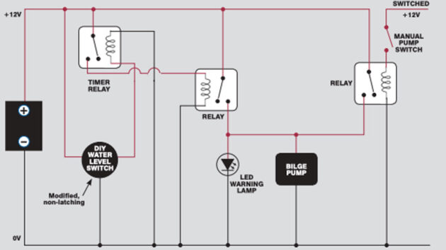
How to install a bilge pump: Schematic wiring diagram for Charles Morland’s bilge pump set-up on his motor-sailer Hedda
On the circuit I designed the automatic switch is wired through a fused, ‘always on’ supply, while the manual feed is wired via the normal switched main fuse panel. The wiring for the relays was taken to normal automotive relay sockets. The sockets slot together to form a bank of the required length and were fixed high up inside a wheelhouse locker to keep them dry and physically protected. By using sockets instead of taking the wiring directly to the relay terminal I can, should a relay fail, replace it quickly – even in a rough seaway – without touching the wiring in what is quite a complex circuit.
As the sensor draws a very small but constant current, and the bilge pump itself draws 8A while operating, I aim to fit a small solar power panel to ensure the service battery is constantly topped up.
How to make a DIY bilge alarm switch
Zoran Gloznic builds a budget bilge alarm switch

Installing a Wavestream 1 bilge filter
Dirty, oily bilge water from your boat’s hull can be filtered to protect marine life. We talk to sailors who…

Bilge pump troubleshooting: getting the float activation switch to work
Zoran Glozinic does a bit of bilge pump troubleshooting to try and work out why the float-activated switch on his…

Best bilge cleaners: how to clean an oily, smelly bilge
Ben Meakins gets down and dirty in the pursuance of the most effective way to clean oily, malodorous bilges
Want to read more articles like How to install a bilge pump on a boat?

A subscription to Practical Boat Owner magazine costs around 40% less than the cover price.
Print and digital editions are available through Magazines Direct – where you can also find the latest deals.
PBO is packed with information to help you get the most from boat ownership – whether sail or power.
-
-
-
- Take your DIY skills to the next level with trusted advice on boat maintenance and repairs
- Impartial, in-depth gear reviews
- Practical cruising tips for making the most of your time afloat
-
-
Follow us on Facebook, Instagram, TikTok and Twitter