




Following fuel injector problems, Mike Corp cleans through his Nauticat 311’s diesel system to ensure smooth and reliable running
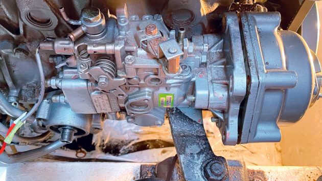
For the last 25 years John and I have avoided any fuel problems, but when the engine wouldn’t start after an eight-hour voyage, a full fuel system clean was the only way to get it running again.
Initially, we start with the injectors, removing them to get a better look at the problem. The valve assemblies were black and the injectors were handed over to a local diesel expert. Their report described seized needle valves in the valve assemblies which he was unable to free, and the specialist suggested that we need four new valve assembly units. New filters were added, and with the new valves and cleaned injectors we were able to return to Brixham.
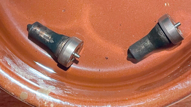
Fuel system clean: The four valve assemblies were blackened and were not delivering fuel to the cylinders. Credit: Mike Corp
A year later and the problem returned – the engine wouldn’t start again. Despite adding Marine 16, the fuel was so infected that once the injectors cooled down, they seized solid and failed to work. Unwilling to shell out another £700, and wanting to avoid future disruptions, we decided to clean the fuel system; the injectors, supply pipes, filters, fuel tank and finally the high-pressure injector pump ourselves.
Fuel system clean: Servicing the injectors
The Yanmar 4JH3-TE has four direct injectors and on the Nauticat 331 they are relatively easy to access. The injector pipes are loosened at the pump and injector end and swung to one side, revealing the two securing nuts holding the injector retainer in place.
To remove the injectors, some people suggest leaving the loosened retainer in place, isolating the fuel supply to the pump and turning the engine over. The compression pressure should be sufficient to break a tight injector from the cylinder head. Fortunately, we were able to fit a spanner on the flat side of the injector body and a gentle rotation was sufficient to loosen and remove the injectors.
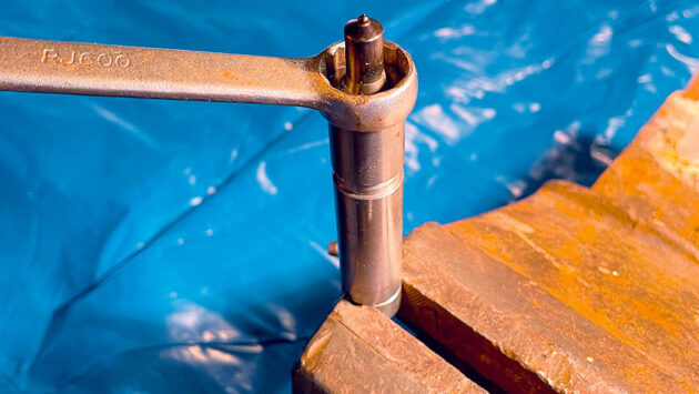
Carefully loosen the nozzle nut or, if no vice is available, use two spanners. Credit: Mike Corp
Disassembling the injector requires a vice (or two spanners) to grip the housing while removing the nozzle nut. When the nozzle was slack, it was unscrewed over a large tray in case the shims, spring and locating pins fell out. The tightly fitting needle valves were seized in the valve assembly and, as in the previous year, the valve assemblies were black with burnt diesel.
Online, various solutions have been described for freeing the needle valve from the nozzle assembly. They included forcing brake cleaner through the injectors or cleaning the injector holes with a fine piece of wire. Neither of these seemed practical and pushing a wire through each spray hole is not advisable; if the wire snapped, the nozzle assembly would need replacing. And the injector spray holes are so small that identifying each hole is difficult when a nozzle is covered in burnt fuel.
Searching the internet for a suitable cleaner, we found Liquipak Heavy Duty Degreaser. We decided to give it a try and ordered a five-litre container intending to use it later when cleaning the fuel tank.
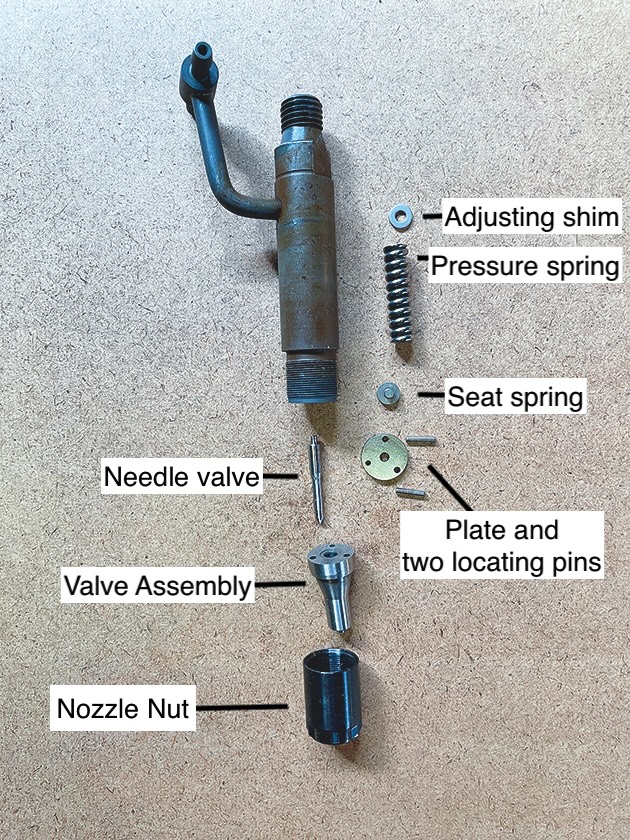
Fuel system clean: Parts of the cleaned injector and in their re-assembly order. When the plate is fitted to the injector body, the needle valve protrudes through the central hole against the spring seat. Credit: Mike Corp
The seized nozzles were left to soak in a jam jar with the Liquipak and almost immediately we noticed dirt falling away. After a few days it was possible to remove the needles from their housing.
The rest of the injector parts were soaked in the same degreaser. Most of the dirt had been loosened by the cleaner so wiping the needles and assemblies with a clean cloth soaked in it was sufficient to finish the job. The injector was left in clean Liquipak and then reassembled, ensuring there was no sediment on the parts.
The original shims were used during reassembly of the injectors. With the needle valve in the valve assembly, care is taken to fit the locating pins in the two larger holes before joining the assembly with the injector body.
Pressure testing the injectors
As helpful as it had been, we wanted to pump out the Liquipak and replace it with diesel, the injectors’ natural lubricant. The injectors were then pressure tested with an injector pressure tester acquired from the internet for about £70.
The Yanmar recommended injector opening pressure is shown in the table (above). Adding or removing a 0.1mm shim would increase or decrease the injection pressure by the indicated values.
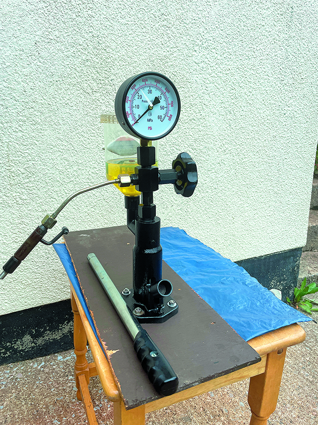
Yanmar supplied injector nozzle opening pressures in MPa and kgf/cm² but seems to prefer the latter. Make sure the scale of the pressure tester is compatible with your injector-supplied information or some conversions will be required. Credit: Mike Corp
The four injectors had the following psi pressures: 3,120, 2,844, 2,560 and 2,550. For the three with low opening pressures, we added a 0.1mm shim to injector two and a 0.2mm shim to injectors three and four bringing all three within the recommended range.
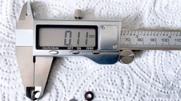
The calliper shows a shim thickness of 0.11mm, equivalent to about 270 psi pressure. Credit: Mike Corp
Each injector has five spray holes with a diameter of 0.22mm evenly spread around the nozzle. The manual shows an example of a good and bad spray. With a cleaned working injector the aim is for five uniform sprays during each opening pressure. The spray appears quickly and can be hard to see, but we were satisfied with the output and noted that the injectors held pressure without any dribble.
Cleaning the fuel tank
On the Nauticat 331, the 250lt fuel tank is built into the boat structure; there are no access plates and it’s not possible to access the tank top. The tank is 1,200mm long and 622mm high with a curved rear area where it fits into the hull shape. There are two baffle plates 400mm from each end so drilling into the tank to fit access hatches required careful measuring to ensure each hole is central in each of the three areas.
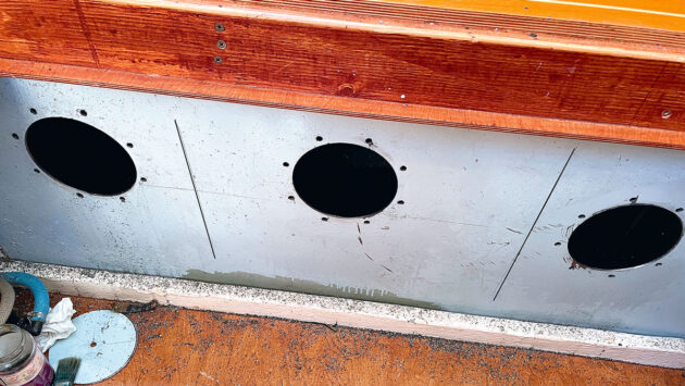
The vertical lines indicate the position of the tank baffle plates. When deciding where to place the holes, we considered our ability to hold the drill square-on to the tank while avoiding any fittings that could not be removed. Credit: Mike Corp
Guidance supplied with the access panels advised drilling the eight securing holes with a supplied template, and then drilling the large access hole centrally between the eight holes. Our hardened steel drills struggled with the 3mm steel tank; we acquired cobalt drill bits which quickly cut through the steel.
While working out the centre point between the eight holes we noticed that the weight of the electric drill had led to some holes becoming elongated. It became even more critical to judge the true central position for the large entrance hole, otherwise the sealing gasket may be to one side and fail to hold fuel in the tank.
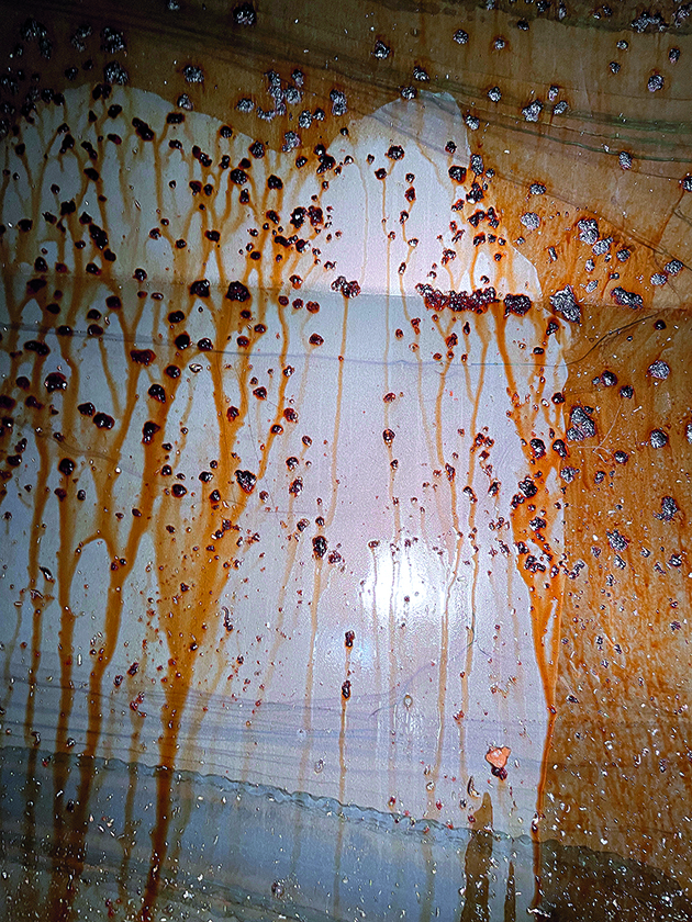
Fuel system clean: Some Liquipak was splashed inside the tank and within minutes dirt started to drain away, although it took days for John to remove the gunge using a mop with a shortened handle. Credit: Mike Corp
We selected three access plates with an 8in (203mm) diameter requiring 6in (152mm) holes cut in the tank. Our 6in hole saw wasn’t up to the job, so we used a cobalt hole saw. Drilling with such a large diameter hole saw into steel is very challenging with the lubricating fluid (clean engine oil) and metal fillings flying around the area (make sure you wear the appropriate PPE). Once the protective sheets were removed, we continued to see metal fillings scattered around the area for days afterwards.
The tank was filthy and had accumulated detritus over the last 20 years. It took several days to finish the tank, including revisits to clean the parts we’d missed.
Cleaning the fuel supply
Within the tank the fuel pick-up pipe and fuel level sensor were cleaned with Liquipak. Some fuel supply pipes were replaced. Normally we’d just replace fuel filters, but we decided to disassemble and inspect the internals of the (Separ), the first filter in the fuel flow.
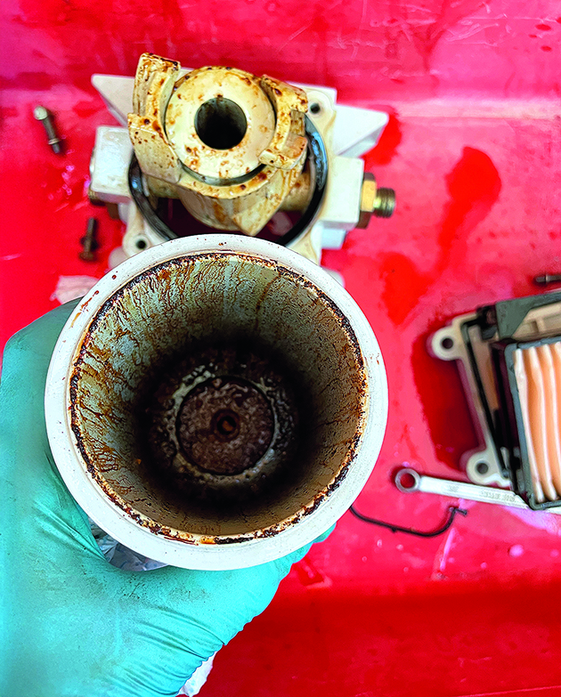
Fuel system clean: Normally John and Mike would just change the square filter element at the top of the Separ filter unit and look no further, but it’s clear the internals were badly contaminated. Credit: Mike Corp
It was seriously contaminated as was the lift pump/filter housing used for bleeding the system. Both were coated in old red diesel and gunge. New filters were inserted and a third Racor-style fuel filter was added to the system.
High-pressure pump removal
With so much gunge in the fuel system it seemed only sensible to clean the whole fuel system and remove and service marine engine pump. We can do most engine jobs, but we did not have the experience or the specialist equipment to disassemble, clean and calibrate the rotary pump. Our only task was to remove it. The engine was set to TDC (Top Dead Centre, so the number one cylinder’s piston is at the very top of its stroke) and the pump housing and engine body were marked to help with re-installation and timing. Primary bits (injector pipes, solenoid wire and a retainer bracket support and bolts) were soon removed. We removed the engine oil filter and loosened its housing to free up more room for the pump. All that remained was to remove the pump, an easy job or so we thought.
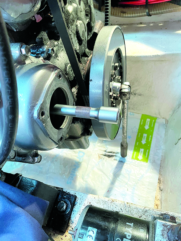
The hanging bar is attached to the 22mm damper nut and was trapped against a wooden block in the bilge. A much longer bar (not inserted here) was attached to the 19mm pump nut and used to eventually loosen the injector pump nut from the timing wheel. Credit: Mike Corp
Removing the 19mm nut that holds the pump to the timing gear was a challenge. While trying to slacken the nut, the engine rotated. Eventually we stopped the engine from rotating by jamming a bar from the damper nut to the bilge floor. The pump securing nut still resisted our efforts. We considered applying heat to the nut, but realised this might damage the timing wheel. It took three visits to the boat to finally remove the nut by using our weight and actually standing on the bar.
With the retaining nut removed, the pump remained firmly seated in the tapered timing gear. An extractor was fabricated, but it bent under the load. We then borrowed a more heavily constructed extractor, which also failed.
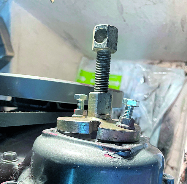
The heavy-duty extractor cracked from the pressure and had to be repaired before it was used to remove the pump. Credit: Mike Corp
After welding the damaged extractor, we attempted removal again, this time applying slightly less tensile load to the threads while simultaneously striking the end of the bolt with a hammer. This combination proved successful.
The pump was serviced by a local company, which reported that the internal components were heavily contaminated with sludge, and that the fuel lift pump– integral to the high-pressure pump – was completely seized.
Injector pump installation
Reinstalling the pump was remarkably easy. The rotary pump services all four injectors in one complete revolution. Consequently, providing the engine is set to TDC the pump can be inserted into the pump housing, ensuring that the keyed shaft slides into the timing gear.
We used Loctite for the 19mm nut that holds the pump into the timing gear. We couldn’t torque the nut due to insufficient working area, so we relied on applying as much pressure as possible. The direction of rotation of the pump would mean it is unlikely that the nut would unwind.
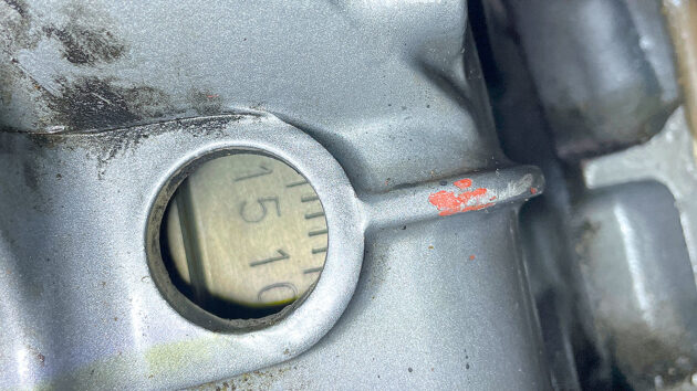
A hole in the flywheel housing for checking the timing is very low down on the starboard side. It’s probably easier to check it using a mirror and torch. Credit: Mike Corp
With the pump-to-timing wheel nut tightened, we slowly turned over the engine until the flywheel showed 13° bTDC (Before Top Dead Centre). The recommended setting is 13 ±1° bTDC. We then rotated the pump body against the pressure of the injector pipes so that the timing marks we had made before removal all lined up. The pump securing bolts were tightened, the fuel system bled and the engine started.
Considerations
We wore protective clothing and gloves while carrying out diesel-related jobs – we’d have been foolish not to. With a pressure of 3,000+ psi we kept our fingers away from the injectors while pressure testing. Pressure testing led to vaporised diesel flying around so these jobs were conducted outside and not in the garage.
The described injector opening pressures are close estimates. During pressure testing, the indicator needle is not held but fluctuates wildly so we repeated pumped before we could be confident about the pressure that opened each injector.
We wondered how accurate our £70 injector pressure tester would be. We had no way of calibrating the tester. However, when we tested the new backup injectors they were all within the recommended pressure, and one of the old injectors was close to the 3,129psi documented pressure.
Cost of new injectors and supplied tips
By soaking the injector nozzles in a cleaning liquid we eventually freed seized nozzle assemblies. We didn’t ponder too long over why a specialist company claimed they were beyond repair. The cost of four replacement nozzles was over £700; we used £15 worth of Liquipak Heavy Duty Degreaser to clean the injectors and the fuel tank. We later sourced four new complete injectors for £216, presumably from China. We have successfully run the boat with the cheap injectors, but as we are unsure of their longevity they are reserved for backup.
Before drilling into the fuel tank we removed any obstacles including a battery and box. The area was covered with sheets and stuck down with Duck Tape.
During clean-up, a vacuum cleaner hardly touched the oily metal fillings, but a magnet covered in thin paper worked perfectly. We removed the paper from the magnet and shook the metal into a bin. The Nauticat manual describes the fuel tank as constructed from stainless steal, but we observed spots of rust both inside and out.
We now realise the importance of checking/cleaning the internal filter bodies as well as the annual filter changes.
Over the years we’ve done many unpleasant jobs on the boat, including changing the heads and associated pipes, and removing many coats of antifoul. All are difficult jobs, but none compare with drilling holes in the tanks and cleaning the tanks and the mess. A powerful (not battery) drill is required which seemed to become heavier while working! When drilling the large access hole, the drill would often kick back which placed a lot of strain on our joints. One of us strained a wrist and had to stop working with the drill.
Why did we get diesel bug?
In 2004, the UK Government mandated the addition of FAME (Fatty Acid Methyl Ester) to diesel which has led to an increase in diesel-related engine issues for boat owners. This is reflected in the number of diesel bug-related articles and letters in the marine press, the increasing use of fuel polishing kits and marine companies offering diesel cleaning services.
For us, a complicating factor is leaving fuel tanks part-filled over the winter season with more opportunities for moisture to creep in (Ed’s note: advice is now to leave fuel tanks as low as possible over winter). Also, we have probably been less than efficient with regular filter checks and fuel system monitoring.
Costs and parts
- Darwendiesels.com. The parts ordered were: one Shim Set £5.94; four Seat Nozzles £19.82; and four Heat Shield Protectors £44.11, totalling £78.82 including postage. It proved impossible to source shims locally with dealers stating they couldn’t get them and resorting to recycling shims.
- Seabuilt.com manufactures access plates with instructions for drilling and fitting. Mike was unable to source the kit in the UK and contacted chmarine.com in Ireland. The cost, including delivery, was €894 for a three plate kit. They can be sourced directly from the USA company.
- Liquipak Heavy Duty Degreaser. A 5-litre container was about £15.
- Cobalt drills cost about £10 each from a local supplier; we used four. A cobalt hole saw costs about £20 – only one was necessary.
- Separ.co.uk supplied a gasket kit for the SWK2000/5 filter for £36.06.
- From the internet, we secured four new injectors costing £216 in total, and the injector pressure tester cost £70 in 2024. The Racor-style fuel filter was about £40.
- The high-pressure injection pump was cleaned, calibrated and fitted with new seals for £750.

How should I look after my fuel to beat diesel bug?
Ali Wood gets some bug-beating advice from Marine 16’s Peter Weide and learns why modern diesel requires more attention than…

5 top causes of boat engine failure – and how to avoid them
Jake Kavanagh talks to Sea Start marine engineer Nick Eales about how to avoid the five major causes of an…

How to service a marine diesel engine in 12 simple steps
It was time to service the marine diesel engine on our Maxi 84 cruiser. Knowing how to diagnose and fix…

12 diesel bug treatments tested
Diesel bug can clog filters and starve your boat engine of fuel just when you need it most. Can diesel…
Want to read more articles like Why a fuel system clean was the only way to get my engine working again?

A subscription to Practical Boat Owner magazine costs around 40% less than the cover price.
Print and digital editions are available through Magazines Direct – where you can also find the latest deals.
PBO is packed with information to help you get the most from boat ownership – whether sail or power.
-
-
-
- Take your DIY skills to the next level with trusted advice on boat maintenance and repairs
- Impartial, in-depth gear reviews
- Practical cruising tips for making the most of your time afloat
-
-
Follow us on Facebook, Instagram, TikTok and X