
We’ve made great progress this month, and as a result the hull skin is now complete, save for a lot of fairing – but that’s for another month! Ben Meakins reports
Our Secret 20 was pretty stiff and unyielding even before we fitted any plywood sides, but with the sides, chines and bottom panels in place, nothing moves in the slightest.
See the full set of articles: Building the Secret 20 kit boat with PBO.
You may remember that in the previous article (Starting on the hull skin underside), we installed the supporting structure for the bottom panels – stringers and bow cheek pieces – so for this article our job list started with fairing everything back, installing extra supports where necessary, fine-tuning everything and installing the panels.
That might not sound like much, but it meant lots of planing, scribing of panels, cutting out and a great deal of epoxy work.
The first job was to fair back the structure ready to accept the hull panels before installing chine panels, fairing these back and installing the bottom panels.
The boat’s structure – both longitudinal and transverse frames, with stringers added to support the hull – forms a series of box compartments. Some of these will become lockers and others waterproof spaces.

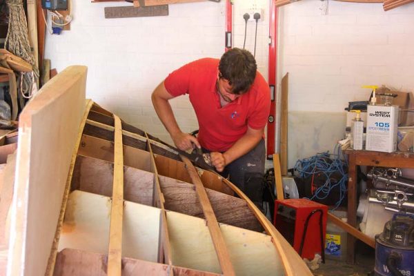
An electric planer made short work of trimming hull sides back to stringer level
Trimming back the side panels
We had stuck the side panels on before we turned the boat over, making sure the top edges were correctly aligned and planed to the level of the deck stringers.
However, we’d left the lower edge oversized so that we could sight along it and ensure it made a smooth curve – much easier done with the boat upside down.
Boat duly turned, we could set to planing it off. This was complicated slightly in that the edge had to be planed in a bevel to allow the chine panels to sit flat upon the chine.
We took the waste off with a Bosch electric planer, which while it appears to be a terrifying, noisy machine can be surprisingly delicate if set correctly.
However, for this job we set it to maximum depth and took the angle off the side panels in this way.
Half an hour and a lot of wood shavings later, the panels were planed to something near their final shape.
The next step was to plane off any wobbles and fine-tune with a nice, long hand plane.
Using a Stanley No5 plane, we could run it along the bevelled chine stringers to plane down the edge of the plywood to match.

The hull sides with the correct bevel planed in to match the stringers
Gluing on extra supports at the bow
From the fourth frame aft, the hull has three faces – side, bottom and stringer – and each edge is well bonded.
However, further forward, the bottom panels butt up to the side panels and must present a smooth curve.
This meant that we needed to glue in some extra supports to give the panels some strength.
We cut notches in the frames to accept a piece of Douglas fir before fitting it with temporary screws.
To ensure that we weren’t wasting material, or having to plane off huge amounts, we bent the timber around the frames to match the hull’s curve.
To do this, we used temporary screws on two of the three frames, but used some rope and a Spanish windlass to pull the front edge in.
This was remarkably effective, and once bent to shape we could epoxy it in using fillets.
With the moment where we attached the bottom panels fast approaching, we realised that it would be worth spending some time in sealing up areas that would become inaccessible or sealed.
With this in mind we painted out lockers and floatation chambers with epoxy, adding fillets and filling voids in the construction.

We glued in extra timber supports for the bow panels, pulled into shape by a Spanish windlass
Sealing inaccessible voids and gaps
WEST SYSTEM had provided us with a tube of their new Six10 product, which they say ‘combines the strength, reliability and excellent physical properties of a two-part West System epoxy with point-and-shoot convenience.’
It comes ready-thickened, and as such it’s supplied in a sealant-type tube, with a special nozzle that mixes the two components.
Application is as simple as squeezing the trigger and pointing the nozzle.
We used it to seal up a tricky area in the bow buoyancy tank, where a void existed between two timber components.
In consistency it’s like a sticky microfibre mix, but was easy to apply and didn’t run.
We tried a few sample fillets, which came out well – but as it has less filler in than you’d usually use, you need to use more glue to achieve a good radius. It is sticky enough to form a useful fillet.

The Six10 epoxy came in a cartridge with a mixer nozzle

This was good for sealing hard-to-access voids and gaps

Our test fillet proved good and strong when it had cured
Working on the chines
Fairing chine stringers
For the chine panels to attach properly, the upper and lower chine stringers need to present a flat surface.
As installed, there were some variations.
The angle was generally correct at each frame, but in between there were some areas where the stringers hadn’t taken up the correct twist or angle.
To rectify this, we took out the long planes again. Using the plane bed as a straight edge showed us how much needed to be planed off in each area, and a few strokes with a very sharp blade soon trimmed each stringer sufficiently that a batten could lie flat across both surfaces.
This took some time, with constant measurements to ensure that port and starboard chines would be the same size.
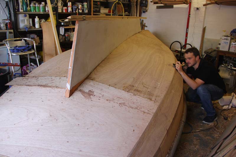
Next up came the transom.
This will eventually have a nice timber veneer attached, but at this point the chine and bottom panels will sit over the top of the plywood transom.
To ensure it fitted, we used long planes to plane off the edges to a feather-edge bevel that would then accept the ply panels, glued on top.

A long plane made sure the top and bottom chine stringers had matching bevels

A stiff batten showed us how to plane the necessary angle on the stringers
Scribing chine panels
The chine panels are supplied well oversized, and need to be scribed to fit.
This we did by holding the panels to the boat with spring clamps while drawing round them, before cutting them to a slightly oversized shape.
The instructions are quite vague about how to achieve a good taper between the chine panels and the curved hull sections forward, and we settled on a long taper running to the third frame.

The chine stringer panels temporarily clamped for marking…

…and before trimming back to reduce the amount of planing!
Gluing on chine panels
With the chine panels cut to size in two pieces, we could glue them on.
For previous gluing jobs we have only primed the areas that will come into contact with fillets or frames, but for these, areas of which will become inaccessible, we primed the whole back side of the panels before applying thickened epoxy to the frames and stringers and installing the panels using clamps and temporary screws.
Planing back chine panels
When the epoxy had dried, we could plane back the edges to match the hull sides and prepare for the bottom panels.
Once again, the electric planer came into its own to trim off any over-long panels, before a No5 jack plane could be used, bed resting on the surrounding structure, to trim back the edges of the chine stringers to match.
Looking along the panels showed up any wobbles or inconsistencies that could be removed with a very sharp plane.

Clamps and temporary screws with penny washers held the panel while the glue set

A long plane helped plane the edge of the chine to match the frames and stringers
Bow panels
Fairing bottom stringers and bow chine supports
With the chine stringers on and planed back, we could move on to preparing for the rest of the panels.
The first job was to fair the boat’s bottom stringers to accept the panels.
This meant taking the stringers down to the level of the frames, planing bevels on the frame edges that stood proud and using a batten to ensure the structure was fair, without any lumps or inconsistencies.
At the bow, where the angles mean that the panels will have to take up a big curve, we made sure that the supporting structure was faired so that it matched the curve of the frames and correctly supported the panels.

4mm bow panel primed and ready to fit

We made sure to apply a good bead of epoxy to secure the fragile bow panels
Fitting bow panels
The bow panels are only 4mm thick, which seemed odd – until we realised that they have to take up an incredibly tight curve.
The front of the panel must be vertical where it meets the stem, and the aft end horizontal – a huge amount of twist.
We persuaded it to take up this curve by first planing off the bevel where it met the stem, and fixing it first to the keel edge with temporary screws and penny washers to stop the screw heads pulling through.
This done, we worked slowly from the aft end, adding a screw at a time in lines into the stringers to slowly pull it into shape.
At the bow, the screws needed to be at no more than 5cm intervals in order to persuade the plywood to take the shape.
We had to use a block plane in situ to ensure that it would pull into a butt joint with the hull side panel, trimming where necessary.
Once dry-fitted, we could remove it, prime and add epoxy before refitting.
This time, we added many screws to ensure that the correct shape was maintained – and in particular to take out any ‘scalloping’ along the edge of the plywood.

Both sides fitted – you can see the number of screws needed to force the panel into the correct shape
Fitting middle panels
The middle panels were much easier, with only a small amount of curve to take up.
These fit against the keel, into a recess formed by the edge of a piece of plywood.
This needed trimming back to accept the panel, and the perfect tool for the job was a Bosch oscillating cutter, placed on a piece of scrap plywood, to trim the edge back enough that the bottom panel could fit underneath.
A ¼in chisel and mallet made short work of anything left behind.
This done, we saw that we needed to plane a curve, and marked this by pushing the sheet up to the keel and measuring 15mm in from the edge, later joining these lines with a long, flexible batten and planing to shape.
Thereafter, we marked the position of the stringers and drove in temporary screws to hold it in position.
The outside edge overhangs the chine panel at this stage – but this could be planed back to form the new lower edge of the chine panel once the epoxy had set.

We used an oscillating saw to trim back the keel and open up the recess

A sharp 1⁄4in chisel knocked out any waste and lumps from the recess…

…and we finished off with a sanding block the same width as the bottom panel

Marking the shape of the keel onto the bottom panels with a steel rule
Fitting stern panels and supports
The supplied plywood wouldn’t do the rest of the boat in one piece, so we decided to make it in three parts.
The largest would run forward on both sides from the transom to the back of the keel, notched around this, and running forward as far as possible – with an infill piece on each side to fill the gap.
We laid the panel over the back of the boat, running a pencil around it to scribe the shape, before removing and cutting to shape.
The next two panels could then be scribed and cut out. We epoxied in 30mm strips of plywood to support the join between these panels.
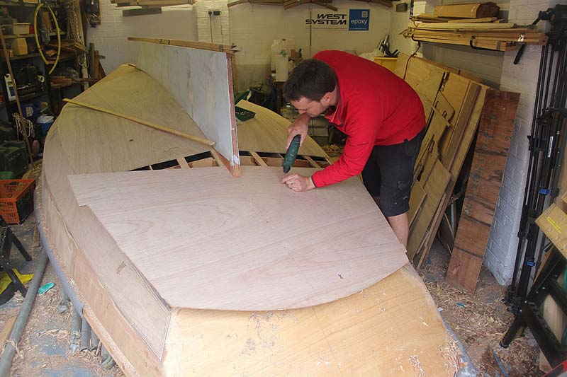
We dry-fitted the aft bottom panel with temporary screws to pull it into shape
Gluing up
All these panels could then be primed and fitted to the boat in the same way as the forward panels.
Planing back edges of chine and bottom panels
And finally, we could plane off the edges of the panels to match the edges of the chine panel and the transom. A few hours’ work with a sharp jack plane had everything trimmed back – and, excitingly, she’s looking like a real boat at last!
Next article: Rounding the bilge
She’s currently looking like a chined plywood boat – and there’s nothing wrong with that – but one of the interesting features of the Secret is her rounded bilge. The design has a novel way of achieving this, despite plywood coming in flat sheets – the chines are built up with cedar strips before being rounded off and faired so that there’s a smooth, rounded turn of the bilge.
As published in the September 2017 issue of Practical Boat Owner magazine.