
Chine in your hands: PBO takes a turn at shaping the project boat’s bilge. David Pugh reports

At the end of the previous article (Completing the hull), our Secret 20’s hull nearly complete, with the plywood bottom panels and chines epoxied in place and planed to shape.
See the full set of articles: Building the Secret 20 kit boat with PBO.
The hull shape looks quite attractive and not dissimilar to many other plywood designs, but the Secret has, well, a secret – she’s actually drawn with a rounded turn to her bilge.
When complete, this has the effect of making her less obviously built from sheet materials and is pleasing to the eye – it’s one of the things which drew us to choose the design to begin with.
It should also add a little form stability by widening the hull at the waterline, but the difference is likely to be fairly insignificant: primarily, the reason is aesthetic.
So, how is it achieved? Clearly, a departure from the plywood used so far is necessary.
The solution proposed and provided for in the kit is to build out the chine with pieces of cedar epoxied in place, then plane it to a fair curve.

A bit messy perhaps, but a solid substrate ready to accept the capping pieces
Alternative methods
After spending so long up to this point carefully fitting and fettling joints, we were slightly put off by the idea of building up the chines with timber in a more or less haphazard fashion.
We considered using foam instead – easy to shape, we could have produced the curved bilge in pretty short order.
The problem would have occurred when we came to sheath the boat – as the foam is intrinsically weak, we would have needed much more glassfibre to add strength to the chine area than required elsewhere on the boat.
Some form of strip planking could also work, but would be unreasonably tricky in such a small area.
We had to conclude that the proposed method was the best one: cedar is both light, strong and easy to work, so should be comparatively straightforward to form into the rounded shape required while still providing a firm substrate for the glassfibre sheathing.
Angled battens at the top and bottom…

…with strips filling the centre gap

Fettling the strips to fit the lower batten
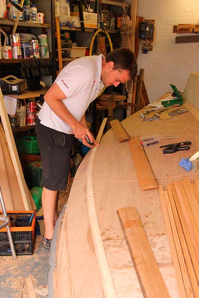
Building up the chines
The kit provided some long battens, sawn at an angle to fit at the edges of the chine panels while continuing the line of the bottom panels and hull sides.
These were clearly the first things to fit, so we fixed them to the chine edges with temporary screws.
The cedar bent easily to the curve of the hull, and left us with a rectangular channel to fill with square section timber.
To fill the gap, we had some longer lengths of 19mm square cedar, plus some boards of a similar thickness, about 1.2m long by 100mm wide.
To start with we offered these into the gap, but the spaces left between the straight edges of the boards and the curved battens would have been challenging to fill without resorting to too much epoxy.
To solve the problem, we used a table saw to rip all the boards down into 20mm strips.
These could bend easily to fit the curves required, leaving only the gap left by the difference in curvature between the upper and lower edge battens to fill.
On the port chine we dry-fitted all the timber before epoxying it in place, but the method worked so well that we built the starboard chine straight onto wet epoxy.
This saved a lot of time and we got away with it, but it’s pretty nerve wracking as you need to get everything right first time.
We found that the table saw was extremely useful for quickly cutting long tapers on lengths of timber.
We also used slow hardener to give us plenty of working time with the mixed epoxy, and of course an electric screwdriver to put in the screws to hold the bent timber strips.
This tool is a bit of an unsung hero of this project – without its aid our arms would probably look like Popeye’s by now!

Planing the strips with a jack plane…

…left a clean, even surface…

…ready for the capping strips
Adding the curved cappings
The kit also provided some lengths of cedar roughly bevelled to build up the apex of the curve.
Offering them up showed us two things – firstly, that although they were around 1.2m long, it would be accurate enough simply to glue them in place along the centre of the chine, and secondly that our strip-built surface was too uneven to avoid a messy epoxy joint.
We solved the latter by planing a couple of millimetres off the chine with a jack plane, leaving a clean, smooth surface to accept the new timber.
Having primed both sides, we then epoxied the capping strips in place, holding them in place with temporary screws while the glue set.

Our home-made tool gave the chine angle

To make templates, we scribed the circle…

…drew the chines with a station pointer…

…and cut them out.
Measuring the curve
The kit comes with two templates to help shape the chine, one for the forward part and one aft.
The problem is that they only offer an average of the curve required over a considerable length, so we went back to basics to see if we could find a more accurate way to template it.
Ideally, the curve should be a circular arc, with the radius of the circle changing to accommodate the width of the chine panel.
We realised that by using a simple tool like a giant pair of dividers we could measure the angle between the side panel and bottom panel, and the distance from the pivot of the dividers to the edge of the panel: the point where the curve should begin.
The maths runs as follows, where x is the distance from the pivot of the dividers to the edge of the chine, d is the distance to the top of the planed curve, θ is the angle measured by the dividers and r is the radius of the required circle.
tan(θ/2) = r/x, so r = x tan(θ/2)
cos(θ/2) = x/(d+r). Rearranging
and substituting for r gives:
d = x/cos(θ/2) – r = x/cos(θ/2) – x tan(θ/2)
Simplifying the above, we get the following three dimensions to help us draw the curve:
r = x tan(θ/2)
d = x (sec(θ/2) – tan(θ/2))
arc length = r(π – θ)
when θ is measured in radians.
The (π – θ) term gives the angle at the centre of the circle – the other two angles in the quadrilateral made by the dividers must be right angles, because the divider arms are tangential to the circle.
We used this number more as a sanity check than for accurate measurement.
Tools and templates
I set up a simple spreadsheet on my phone to make the calculations quickly, and we tried the idea out on the boat.
To make the tool we modified a navigation device from Nautrack, a sort of one-armed plotter which had come into the PBO office for testing decades ago.
With a protractor attached to a long arm (complete with a scale in inches), pivoted to a disc with an alignment line, all we needed to do was trim away some of the protractor disc, which would otherwise have touched the hull and thrown out the measurement, and add an extra arm.
It proved ideal, as the scale on the arm made measuring the chine edge distance easy. That’s a handy tool I’ll add to my odd home-made tools drawer for future use!
This approach worked well, and we used it to cut out eight hardboard templates to fit the curve, spaced at half-metre intervals along the chine.
To mark out the templates, we used a compass to draw circles at the calculated radius, and a station pointer set at the measured chine angle to show the angle of the hull.

Measuring the apex offset to find the amount to plane off as a starting point

Checking the fit with a template

Sandpaper removed any final irregularities
Planing the curve
A bit like rounding spars, it’s important to try and plane the chine down as a series of flats.
We found the apex offset distance d from the above calculations really useful to give us a starting point: using our angle measuring tool set against the hull and measuring down from the pivot point showed us how much we needed to plane off before we could begin rounding the bilge.
Depending on how much material needed to be removed, we measured this distance at each templating point and planed it flat with a power plane or jack plane.
By eye, we then planed flats either side, and used the templates to help shape the curve.
The lengths between the templates we then faired in by eye; a long plane is a real help here, first set coarse to remove plenty of material, then on a fine setting for final smoothing and shaping.
To remove any flats left from planing we used 60-grit paper pulled across the grain, which made short work of any irregularities.
To tidy up, we switched to 80-grit paper used along the grain.
Passing a hand over the wood proved a very sensitive way of finding lumps and bumps, which could then be sanded smooth.

The centre section was a bit low, and needed some epoxy filler

The filler is easily sanded to leave a smooth curve
Final fairing
Although planing and sanding achieved 90% of the desired result, towards the centre of the chined section there wasn’t quite enough timber to complete the curve.
After sanding, we vacuumed away all the dust and applied a layer of fairing filler, using low-density microballoon-based powder mixed with WEST SYSTEM epoxy.
This is strong but easy to sand, so we were then able to return to the boat and complete the curve in this area.

The rounded bilge complete, subject to final fairing
Conclusion
The result is very pleasing. When planed back there’s not a lot of extra timber, but it takes away the angularity of the chine and gives the hull a more traditional look.
The transom in particular should look stunning with its new shape, especially once we have applied the transom veneers. That’s a job for next month.
As published in the October 2017 issue of Practical Boat Owner magazine.