
After seven years of regular use, a saildrive gaiter should be changed before it deteriorates to let water through the hull, warns Tony Davies

The saildrive revolutionised engine installation in many smaller vessels.
The combination of a compact engine/drive package and relatively easy installation with no propeller shaft alignment to worry about has made them very popular.
However, like every other piece of onboard equipment, the saildrive requires regular maintenance.
This consists of changing the oil annually, checking for water ingress (identified by the oil being a milky white colour), checking the external fairing gaiter to ensure it is still firmly in position and the vitally important sealing gaiter that actually prevents water from entering the boat.
Originally Volvo recommended changing this gaiter on an annual basis, but the current recommendations are for an annual inspection and a change once every seven years (unless an inspection shows early deterioration).

All services (ie wiring loom, starter cables, calorifier) must be unplugged or disconnected
Changing the saildrive gaiter is not difficult although it may be time consuming and as it’s the only thing that stands between the boat and a watery grave it’s essential to do the job correctly.
If you are in any doubt about your ability to complete the job properly, leave it to the professionals.
This job illustrated here was carried out on a Volvo MD2002 18hp twin-cylinder engine.
The drive is a 120SB/120SC (the 120S has minor differences).
Begin by removing the propeller, draining the oil from the drive and peeling off the outer fairing seal.
Before the engine can be moved all the services must be disconnected.

In the absence of isolating cocks, support the ends of disconnected pipes with ties or tape
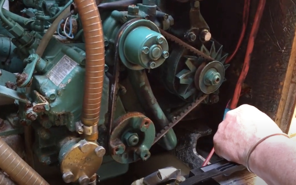
The electrical connections to the alternator are normally combined in the standard wiring loom and can be simply unplugged but the heavy-duty starter cables must be individually disconnected by undoing and removing the securing nuts after the batteries have been disconnected or the main switches turned off.
If a calorifier is fitted for heating the domestic water the engine coolant will need to be drained before the calorifier pipework can be disconnected.
Alternatively, the hoses can be disconnected and quickly plugged to prevent excess coolant loss.
To avoid unnecessary pipework disconnection and draining of the system the remote header tank (where fitted) can be dismounted from the bulkhead and simply laid over the top of the engine with hoses attached.
There should be isolating cocks on the fuel feed and return, and these need to be turned off before the fuel lines are disconnected.

The gear cable is mounted using brackets on the outer cable and a split pin for the inner cable to the gear-change lever
If stopcocks are not fitted and the tank is full, support the ends of the disconnected pipes above the level of the fuel in the tank.
Either tie them up out of the way or tape them onto the bulkhead. Make certain they can’t fall down or the tank may drain into the bilge.
The best way to disconnect the exhaust is to remove the exhaust elbow from the cylinder head or exhaust riser as the pipe itself will be difficult to remove from the outlet.
A riser will be fitted if, like in this example, the engine is mounted low in the boat with the exhaust elbow close to the waterline.
It’s essential to drain the elbow (or riser) by removing the drain plug on the side (or rear).

The remote header tank (where fitted) can be dismounted
If this is not removed, any water lying within the riser will drain down into the engine exhaust passages.
Once the riser has been drained down, the securing bolts on the exhaust elbow can be removed and the elbow lifted away with the exhaust hose still attached.
Undo the small bolt clamping the stop inner cable to the stop lever.
The stop cable outer sheath fits onto its mounting bracket through a rubber grommet. This prevents vibration and insulates electrically.
If the washers are not fitted the grommet and cable mounting may slide out when the stop handle is pulled.

Remove the securing nut on top of the rear drive mounting bracket
To remove the outer cable undo the nut on the outer end, remove the nut and washer and pull the cable through the grommet.
Disconnect the throttle cable which is clamped to its mounting bracket. The gear cable is mounted using brackets on the outer cable and a split pin for the inner cable to the gear-change lever.
A washer is positioned between the lever and the split pin to keep the cable in line with the lever.
The water inlet on the saildrive is plastic and will break if due care is not exercised when removing the pipe.
This can be replaced with a ball valve if desired.

Support the engine and saildrive before disengagement
Note, that water inlet restriction points where sediment gathers are located at the openings at the bottom of the leg; on the inlet side of the shut-off valve; in the base of the gearbox upper housing and the hose connection to the engine from the inlet valve where the tube size is reduced.
All these places will benefit from special cleaning while the leg is removed.
Disengage the saildrive from the engine With blocks placed beneath the back of the engine, it is slid forward on the engine beds to uncouple it from the drive.
Move the engine forward until there is access to all the clamp ring securing bolts.
The engine must be uncoupled and slid forward and clear of the drive before the drive itself can be removed.

Tilt the drive backwards when lifting out to allow clearance for the prop shaft
Remove the bolts securing the front engine mounts to the engine beds, leaving the mounts attached to the engine feet.
This allows the engine to be slid forward on the beds when disconnected from the drive after chocks are placed beneath the back of the engine sump to keep the engine level.
Thankfully, engines used on saildrives are generally light enough to be manhandled with some help.
Before the engine is uncoupled from the drive both engine and drive must be supported to ease the disengagement of the drive’s input shaft from the engine drive plate.
The drive has holes in each side of the mounting flange to allow round bars to be inserted so the drive can be supported on blocks.
It may be easier to shore up the drive with blocks beneath the boat.

Unbolt the plate between the gaiter and leg. Note the saltwater corrosion, which will need attention
Note, the height of the supporting blocks to ensure alignment is the same when later reconnecting engine and drive.
The rear drive mount is in two parts. First, remove the securing nut on top of the rear drive mounting bracket.
Next, remove the two bolts that secure the mount to the bed. The bolts holding the engine and drive together can now be loosened and removed.
Using blocks placed beneath the rear, slide the engine forward to uncouple it from the drive.
Move the engine forward until there is access to all the clamp ring securing bolts.
Undo and remove the clamp ring bolts and lift off the gaiter clamp in preparation for lifting the drive.

Use a craft knife to carefully scrape corrosion from the sealing faces of the leg and plate
Note, when the saildrive is lifted out it must be tilted backwards to allow the propeller shaft to clear the slot in the mount.
With the saildrive on the bench, the first job is to remove the locking wire on the four main securing bolts retaining the leg to the gearbox.
These four bolts and the rest of the securing bolts can now be loosened and removed (there is a washer on each).
The gearbox and gaiter can now be lifted off the drive leg. Note, on the 120SB and 120SC drive there is a plate between the leg and gaiter.
Continues below…

How to service a marine diesel engine in 12 simple steps
It was time to service the marine diesel engine on our Maxi 84 cruiser. Knowing how to diagnose and fix…

5 top causes of boat engine failure – and how to avoid them
Jake Kavanagh talks to Sea Start marine engineer Nick Eales about how to avoid the five major causes of an…

Volvo saildrive seal replacement: How often do you need to do it?
Simon Johnson asks: “I’m planning to sail my boat Zeno back to Britain from Corfu next spring and as the…
How the diesel engine works – take a look at Maximus’s Volvo saildrive
Checking the diesel engine after a long lay-up is an essential task before launching any boat, says marine surveyor Ben…
There is no plate on the 120S drive. Lift off the drive coupling shaft and carefully remove the shims between the gearbox and the bearing in the lower housing for refitting on reassembly.
If they’re lost the drive will need re-shimming and this complicates the job. Also, remove the old gasket.
The plate between the gaiter and leg can now be unbolted from the gearbox. Three bolts secure the plate to the gearbox.
Note, if there is saltwater corrosion on the plate this will need cleaning off before all of the bare aluminium is repainted.
All corrosion deposits must be carefully scraped off the sealing faces of the leg and plate of the saildrive.
A craft knife blade is ideal for this although it’s important not to scratch or gouge the surfaces.
The groove that locates the gaiter on the gearbox must also be cleaned of corrosion.

Remember to replace the shims that came out between the bearing and gearbox
Scrape out the worst of the corrosion and then lightly abrade with 1,000 or 1,200-grit emery cloth. De-grease with acetone to ensure the recess is totally grease free to ensure a good grip on the seal.
Protect the drive shaft opening with a rag to prevent corrosion material from entering the gearbox.
The new gaiter can now be assembled dry onto the groove in the gearbox with NO sealant or grease.
Fit a new O-ring to the flange on the plate and then bolt the plate (to 30Nm torque) onto the gearbox dry without any sealant thus securing the gaiter.
Smear both sides of the new gasket with Volvo Permatex sealant (not included in the gaiter kit) and place it into position on the leg.
Next, carefully refit the shims ensuring they are all in place before refitting the drive coupling shaft.
The gearbox can now be refitted to the lower leg. The bolts are refitted in their correct positions.

Refit the bolts and tighten in the correct sequence. First round 10Nm, final 30Nm
The two long bolts go in the holes nearest the aft support bracket. Ensure the four bolts with lock-wire holes go into their correct positions.
The bolts are then tightened in the correct sequence.
Tightening torque for the first round is 10Nm, and for the final round 30Nm.
Thread the new lock wire through the holes in the bolt heads and twist the ends together until the wire is tight to ensure the bolts cannot loosen under vibration.
At this stage, the drive can be refilled with oil before reinstalling into the boat.
Clean and degrease the plinth and surrounding area before bringing the drive into the boat. Moving outside clean and degrease the area where the fairing gaiter fits over the leg and abrade the surface.
Before placing the leg in position check whether the clamp ring will pass over the gearbox; on some models it is necessary to pass it over the leg from the bottom and push it up over the gaiter.

The propeller is refitted and a new anode installed. Job done
The saildrive can now be placed into position.
Use the same blocks as during removal to support the saildrive and it will be in approximately the correct position for re-coupling to the engine.
Evenly tighten the clamp ring bolts (tightening torque 20Nm).
Grease the gearbox input shaft and place the engine onto the mounts.
Engage the gearbox shaft with the engine drive plate while moving the engine backwards onto the shaft.
Select reverse gear and move the flywheel left and right slightly to help engage the splines.
The engine can now be bolted down onto its mountings and all the ancillaries reconnected.
Lightly abrade the inner face of the new fairing gaiter and apply a good quality contact adhesive designed for use with rubber or plastic.
Similarly apply contact adhesive to the cleaned hull area and once tacky push it up and press it firmly into place.
Install a new anode, refit the propeller and the job is finished.
Removing the saildrive unit: step by step

1. Remove the prop, drain the drive oil and peel off the outer fairing seal from the hull.

2. Disconnect all the engine services (ie cables and wiring) and then the exhaust (above).

3. Disconnect the throttle by undoing the small bolt clamping the inner cable to the stop lever.

4. Carefully remove the pipe from the plastic water inlet spigot on the saildrive – it can break easily.

5. With engine and drive supported, remove the bolts securing the front mounts to the engine beds.

6. Remove the nut on top of the rear drive mount and then the two bolts (pictured) securing the mount to the bed.

7. Loosen and then remove the bolts that are holding the engine and drive together.

8. Slide the engine forward to uncouple it, remove the clamp ring bolts and the gaiter clamp.

9. Remove the drive locking wire (inset) and four bolts, then lift the gearbox and gaiter off the drive leg.
Strip down and cleaning: step by step

1. Carefully remove the shims between gearbox and bearing for refitting later, then remove the old gasket and clean up the mating surface.

2. Unbolt the plate between the gaiter and leg. The salt on this seven-year-old gaiter inner ring shows that water has almost penetrated the boat.

3. Scrape off corrosion from the sealing faces of the leg, plate and groove that locates the gaiter on the gearbox. Rags help keep muck out.
Gaiter reassembly: step by step

1. The new gaiter is assembled dry onto the groove in the gearbox with NO sealant or grease.

2. After fitting a new O-ring to the flange, dry-bolt the plate back onto the gearbox

3. Smear both sides of the new gasket with sealant, refit the shims and the drive coupling shaft.

4. Refit the bolts then thread new lock wire through the holes in the bolt heads. Twist the ends together.

5. Refill the oil, clean and degrease the plinth and gaiter area then place back in position.

6. Reattach gaiter collar, slide the engine back aligning it with the saildrive shaft then bolt together.
Time and ability to replace a saildrive gaiter
- Time taken: two days (pro), four days (amateur)
- Skill level: advanced
- Hint: replace all O-rings on drain plugs, fillers, etc. Beware of O-rings stuck in recesses. They may fall out and be lost and with no O-rings there will be leaks.
Enjoyed reading Replacing a saildrive gaiter? 
A subscription to Practical Boat Owner magazine costs around 40% less than the cover price.
Print and digital editions are available through Magazines Direct – where you can also find the latest deals.
PBO is packed with information to help you get the most from boat ownership – whether sail or power.
-
-
-
- Take your DIY skills to the next level with trusted advice on boat maintenance and repairs
- Impartial in-depth gear reviews
- Practical cruising tips for making the most of your time afloat
-
-
Follow us on Facebook, Instagram, Twitter and TikTok