
Geoff Higginbottom replaces the cylinder head on his Volvo MD2030 marine diesel engine

But I was unable to isolate the exact cause before our annual cruise around the Channel Islands and northern France, so we simply kept the revs low while motoring and enjoyed our holiday.
However, while motor-sailing from St Peter Port to Cherbourg, the smell of unburnt diesel increased and just a couple of miles from the west entrance to the harbour we started emitting rather a lot of white smoke.
We limped into Chantereyne marina and were luckily able to berth on the hammerhead, which reduced the amount of time manoeuvring under power and kept the white smoke to a minimum. We obviously needed to address this tout-suite so cancelled our plans to continue onto St-Vaast-la-Hougue and set about investigating a possible defective or blocked injector.
How does a diesel injector work?
A four-stroke diesel engine operates when atomised diesel fuel is injected at very high pressure into a cylinder of heated compressed air. The resulting explosion produces an expanding gas that pushes the piston down, turning the crankshaft, which then turns the gearbox and drive shaft.
The injector has a nozzle with four tiny holes in it, which pokes into the cylinder through the cylinder head. The nozzle contains a tapered needle which controls the passage of fuel. This needle is moved or controlled by the pressure of the fuel from the injector pump.
When the needle is lifted off its sealing seat by the fuel pressure, the fuel passes through the nozzle and atomizes in the hot air in the cylinder which causes it to ignite as described. Any excess fuel not injected into the cylinder is returned to the fuel tank via the leak off pipe.

Surprise breakage
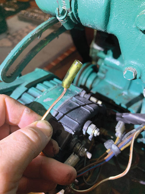
I successfully pulled the front two injectors (of the three), but the aft-most one was surprisingly loose. Diesel injectors should be fitted with relatively high torque, so when I set to removing the retaining nut for the fuel leak-off pipe attached to the rear cylinder, I was genuinely surprised to see the whole injector rotate as well. Inevitably, the result of this rotation was that the brass leak-off pipe broke.
With the three injectors all pulled, a quick inspection of their ports highlighted that the rear injector port was completely blocked with carbon build-up, and I attributed the cause to the loose injector. We also noted that there was a lump of something that looked like calcified carbon still partially blocking the injector port, but this proved impossible to remove.
I cleaned the rear injector port, and made a temporary repair to the fuel pipe using JB Weld before reassembling the system. An engine test confirmed we had, at least, stopped the billowing white smoke.
Due to a lack of brazing equipment on board, which could have been used to affect a more permanent repair of the leak-off pipe, I decided to visit a few local garages and workshops to see if anyone could fashion some kind of repair for me. Unfortunately, I was out of luck.
Plan B therefore was to use the Volvo Penta Action Service (VPAS) to source a replacement part. This was now Friday afternoon before the August bank holiday and we had crew joining us on the following Tuesday ready for a sail back across the Channel. VPAS were very helpful with identifying the correct part number, locating a local dealer, dealing with translation challenges, and getting them to deliver it right to the marina on the Monday. However, I ended up having to pay 200 Euros for a part you can get online in the UK for £50.
With the replacement fuel pickup installed and wine stocks replenished we enjoyed a lovely sail back across the channel stopping overnight in Yarmouth, before continuing on to Portsmouth. Engine power was still slightly reduced, but there was no billowing white smoke.
I knew I’d need to remove the cylinder head in order to identify the foreign object in the rear cylinder injector port, and as the boat would be moving to her winter home in October, we enjoyed a number of weekends in the Solent without incident.
Getting to the root cause

Once the boat was in her winter home at Hornet, Gosport, I could focus on the task of pulling the cylinder head and investigating further. I removed the injectors and sent them off for servicing as well as ordering a cylinder head gasket kit in preparation for what I hoped would be a weekend-long job. Then I set about removing the cylinder head (see the step-by-step guide below) and discovered the true cause of our loss of power.
The engine, which is actually a Perkins unit rebranded by Volvo Penta, has pre-combustion chambers. These make the engine easier to start and also improve fuel efficiency by partially igniting the fuel in a small chamber, before it gets squirted into the cylinder.
The chambers are sealed with conical inserts containing a number of holes which shape the charge as it enters the cylinder. The foreign object I’d earlier assumed was calcified carbon was in fact the remains of the conical cap for the rear cylinder. The good news was it had remained within the pre-combustion chamber and had not entered the main cylinder, as I’m sure this would have proved to be terminal for the engine.
The bad news was this was obviously not going to be a quick fix.
I needed to send the head off to a specialist for repair, so I made contact with a Perkins specialist who informed me that while it’s technically possible to replace pre-combustion chambers in a number of different engines, it was not possible for this particular engine. For my engine, the cylinder head is considered a single part, so Perkins do not make the individual component parts available.
I searched for a second-hand replacement for a couple of months but eventually had to stump up around £1,200 for a new Perkins head.
I did contact Volvo Penta who insisted their heads are machined differently so I should use a Volvo Penta version (at least 20% more expensive). Well I thanked them for their advice and then fitted the Perkins head. So far all is well…
About the author
 Geoff Higginbottom grew up sailing dinghies before moving onto bigger yachts around 18 years ago. After gaining his Yachtmaster he bought his own boat in 2016. A previous career as a Royal Navy Artificer means Geoff is not shy about tackling repairs and upgrades.
Step by step: dismantling a marine diesel engine
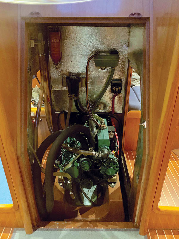
1. Engine access aboard the Bavaria 39 is excellent once the companionway steps are removed. But I regretted not getting around to fitting those engine room lights, so broke out the head torch to see what I was doing.
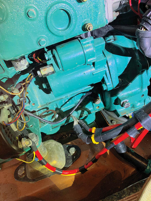
2. For such a major engine strip, my first action was to disconnect the power connections to make everything nice and safe, removing the positive wires from the starter motor and the negative wires from the flywheel housing. This engine is electrically isolated from the saildrive, so there were no concerns about galvanic protection being impeded.
3. Sticking with the electrical theme, next to get disconnected were the water temperature sender, oil pressure sender and glow plugs.

4. Senders disconnected
5. More electrical connections severed before work starts.
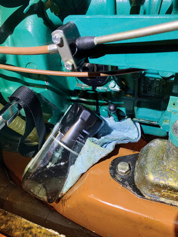
6. Draining the oil is not necessary in order to pull the cylinder head, but I was planning on doing a full service on the engine at the same time, so I removed the oil filter and pumped out the oil via the dipstick using a vacuum pump.
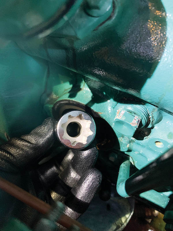
7. The cooling system will need to be drained, however. A good trick with this engine, which has a square drain plug, is to get a 17mm 8-point socket that fits the nut perfectly, then carefully drain and collect the fluid for correct disposal.

8. Fluid ready for disposal.
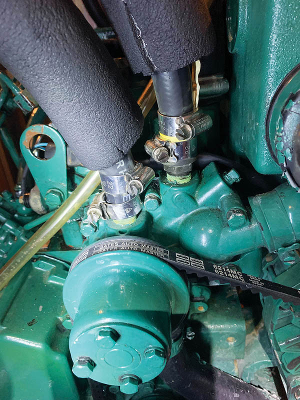
9. With all fluids out of the engine, disassembly can commence starting with the hot water hoses which typically go to the calorifier. The reason these pipes have insulation on them is that we also have a water-based heating system and all the piping is insulated to improve efficiency.
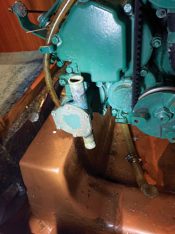
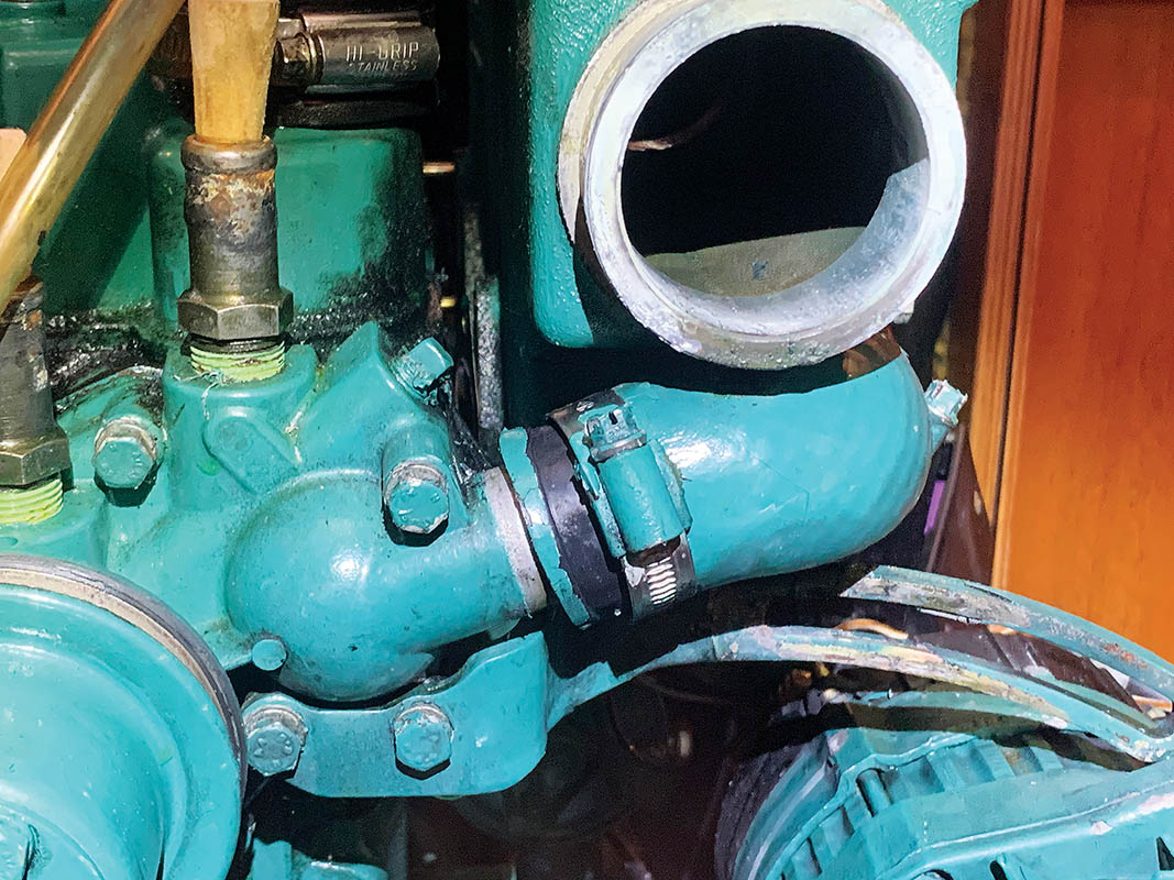
10. The raw water pump does not strictly need to be disconnected but it does improve access and as I had a full gasket kit, I took the opportunity to dismantle and replace all gaskets and seals, as well as change the impeller. The stop-cock for the raw water cooling which is built into the saildrive must be closed before disconnecting these pipes.
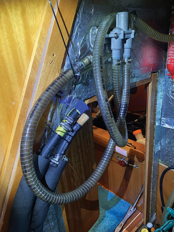
11. All the pipes were then capped off and secured well out of the way to prevent them hindering my access to the engine.
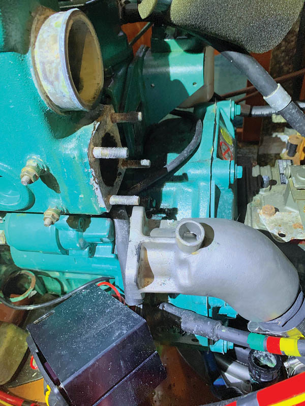
12. The exhaust elbow and associated rubber boots from the heat exchanger were next to come off, but first I had to remove the electrical box in order to gain access to the heat exchanger’s bolts. The insert for the heat exchanger was also removed and set aside for cleaning and inspection.
13. The heat exchanger is held on with four bolts and two studs at the rear. The studs are also used to mount the electrical box. I used two of the nuts locked against each other to later remove the studs from the cylinder head.
14. There are two pipes connected to the heat exchanger, one underneath and one at the front, both connecting it to the water pump. These were showing signs of cracking, so I purchased a replacement kit. I could now see that the front one would be very difficult to replace without removing the heat exchanger, so it made sense to get it done immediately.
15. With the heat exchanger removed, it was obvious that there had been some long-term oil leaks so a full gasket and seal replacement was long overdue. I was now also able to remove the air intake pipe and air filter.
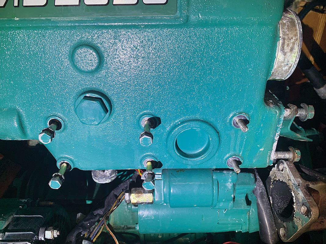
16. The cooling water pump needs to be removed as it spans the head and block. It initially appeared that all bolts were at the front, but after removing the heat exchanger it became obvious that there was one sneaky bolt hiding at the back. This means it’s basically impossible to change the thermostat without first removing the heat exchanger, so I found myself committing to installing a new thermostat as well.
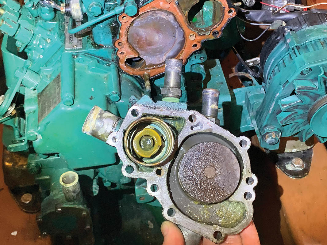
17. With all the bolts removed from the water pump, I was able to tease it off the engine, but there was still the backing plate to think of. It’s tempting to use screwdrivers to prise it off but that method can damage the mating surfaces. It’s best to tap it gently all round with a dead-blow hammer.

18. The backing plate removed.
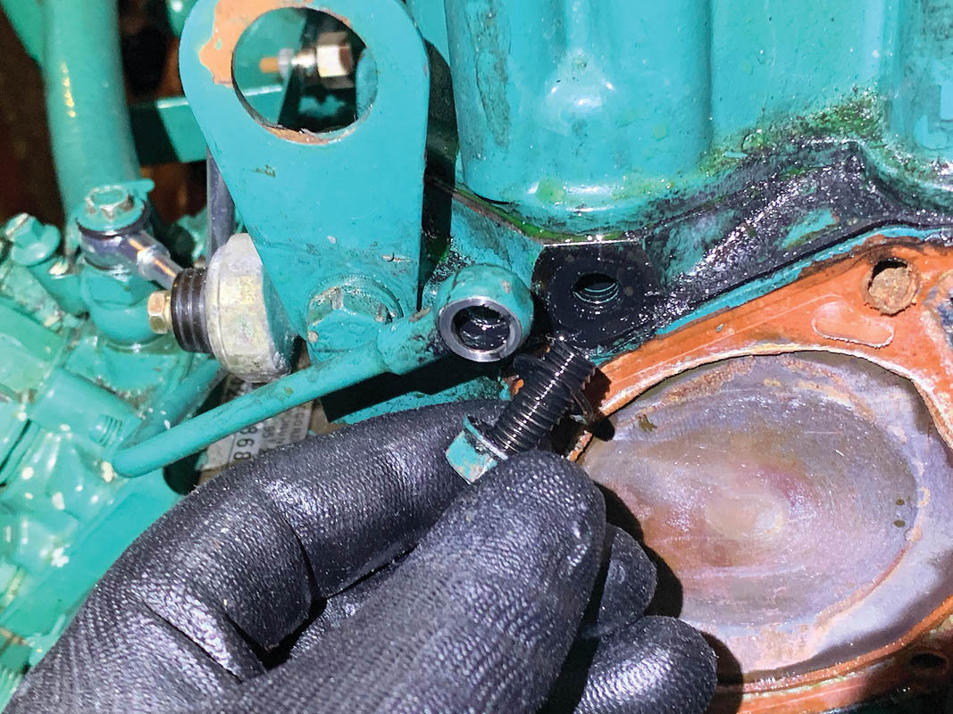
19. The oil delivery pipe feeding the head with oil was next to come off. The hollow screw has washers front and back, so to prevent losing them I put the screw back into the head, then protected the feed pipe from dirt by taping it up.

20. The screw replaced and the feed pipe taped up.
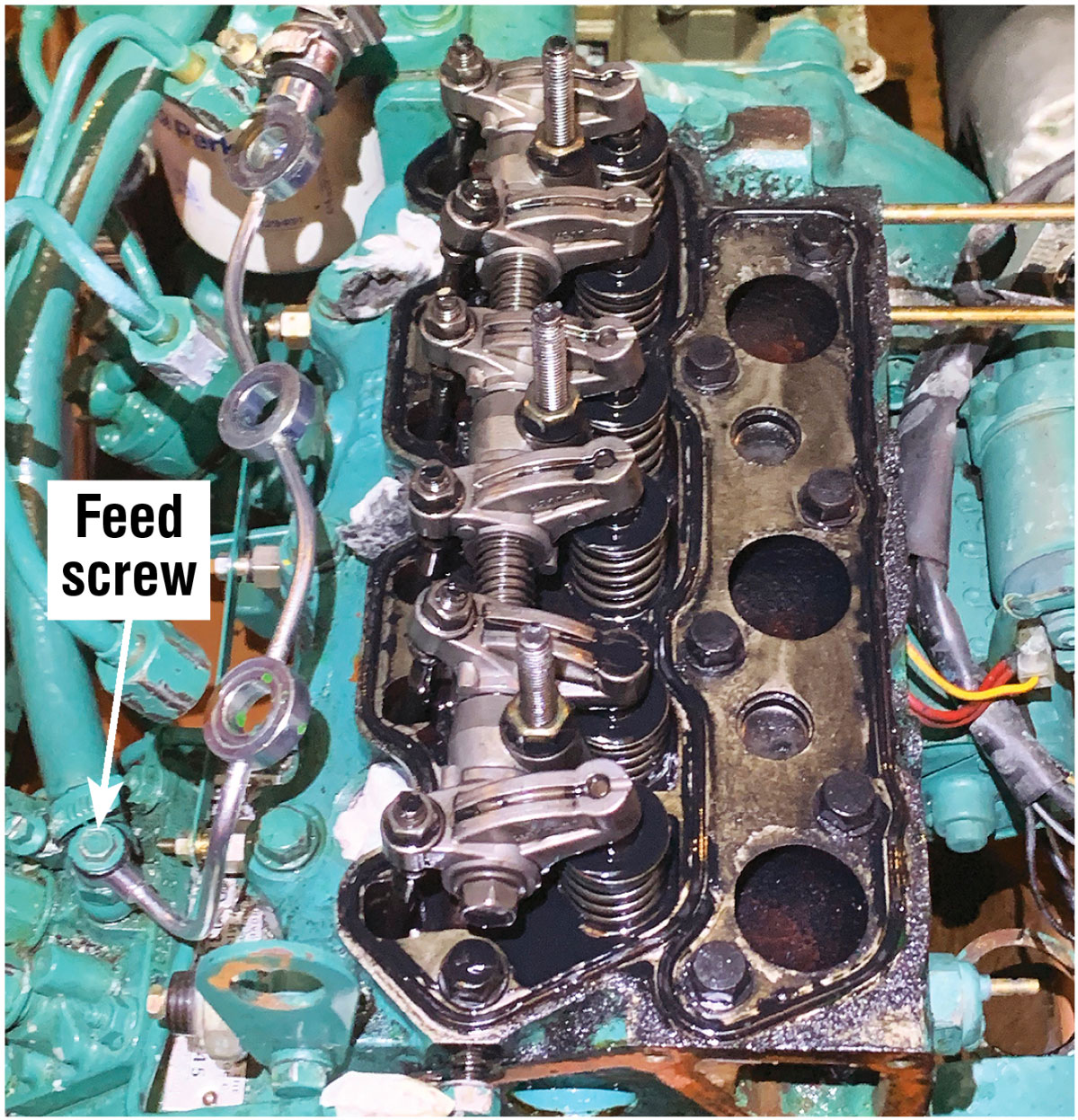
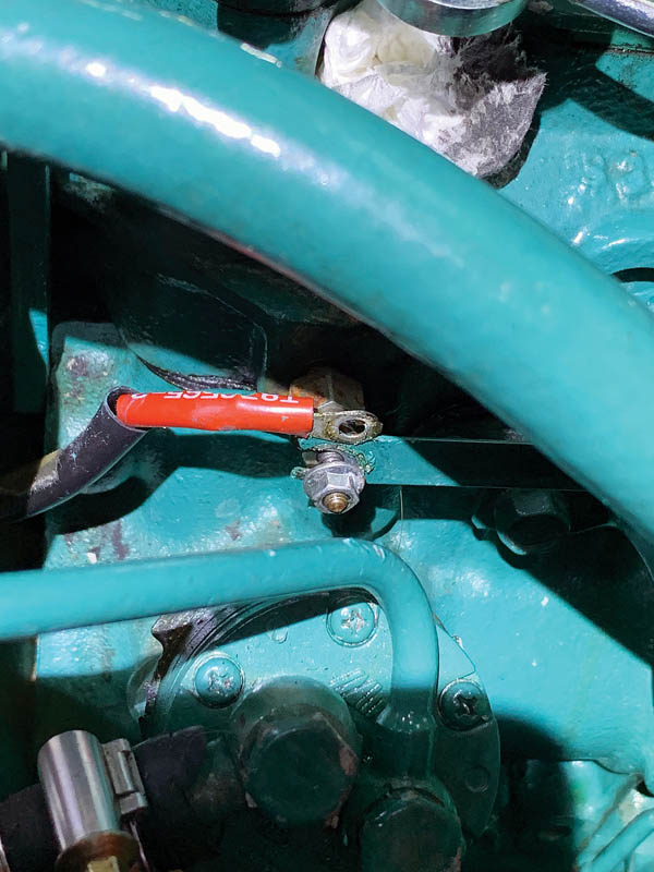
21. Next I removed the valve cover, which is retained by three dome nuts. I’d previously removed the injectors and protected the injector ports from contamination, and the new very expensive shiny fuel leak-off pipe can be seen on the left. This was removed and the feed screw placed back into the injection pump with both washers to prevent loss and contamination.
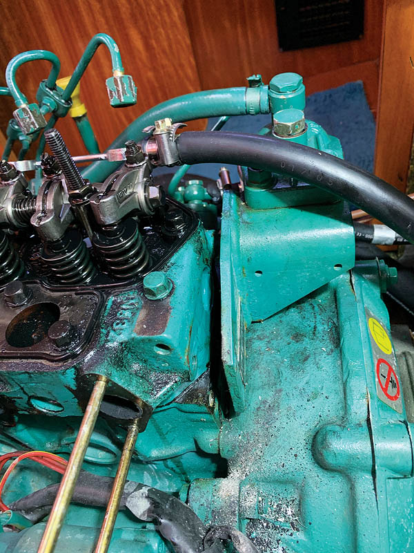
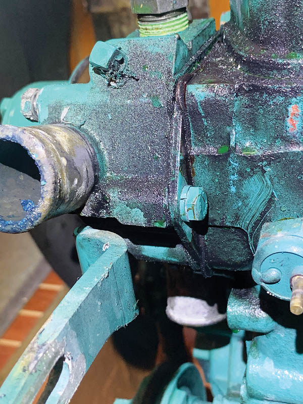
22. At the rear of the engine the bracket that holds the fuel filter spans the block and head so also needs to be detached. In hindsight I should have removed this before I tackled the exhaust elbow as it would have allowed easier access to the bottom inboard bolt which can be tricky to get to. This does not need to be completely removed, just unbolted to allow the head to be removed.
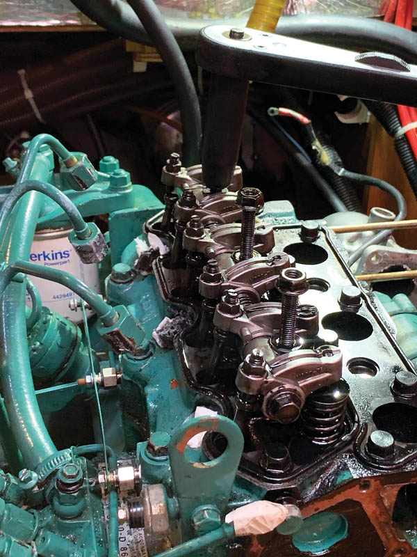
23. The rocker arm assembly needs to come off as it covers a number of the cylinder head bolts. An extra deep socket makes this process easier. While a spanner could be used for disassembly, a torque wrench is required when re-fitting, so a socket really is required. With rocker arm off the push rods simply lift out of the block. Store them carefully so they can go back in the same order they came out.
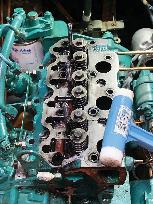
24. When a cylinder head is fitted the bolts need to be tightened in stages in a specific order. Maintenance manuals always cover this, but they generally don’t mention it for removal. I was advised many years ago by an ‘old boy’ engineer to release the head bolts using the same pattern, cracking each bolt first, then loosening in a couple of stages. Once the bolts were removed the head needs to be broken free by tapping all round with a dead-blow hammer – not prised off which could damage gasket mating surfaces.

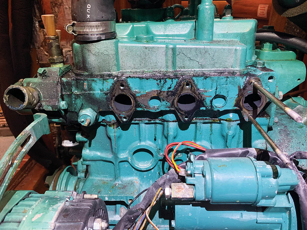
25. With the head now removed it was obvious that I had a bigger problem than some simple carbon build-up. Note the gaping hole on the rear cylinder (on the left in this image) which is where the pre-combustion chamber insert should be.

26. A closer look shows the pre-combustion chamber insert is rattling around inside the chamber instead of sitting proud like its neighbour.