Gilbert Park shows how he installed a new Raymarine autopilot on his Trusty T23 motorboat
You don’t need a professional to fit your Raymarine autopilot. Gilbert Park shows you how
My Trusty T23 was great for enjoying Chichester Harbour at 4-5 knots, but going any further was a bit of a strain.
Every time you let go of the wheel she would quickly veer off course.
If there’s more than one crewmember this isn’t such a problem, but I tend to cruise alone and make long voyages so help was going to be needed from an autopilot.
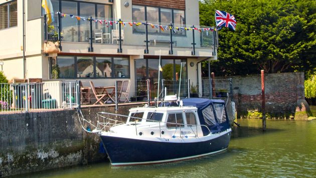
Gilbert’s Trusty T23 used to veer off course every time he let go of the wheel so decided to fit an autopilot. Credit: Gilbert Park
Initially, I had to find the size of the steering cylinder to work out which autopilot kit I needed.
At a pinch, the smallest one might have worked for my Trusty T23, but there was certainty with the next size up, so I ordered one.
Autopilots are usually called ‘George’, probably after their inventor George DeBeeson, and can be a better helm in a motorboat than any human, saving on fuel as well as general wear and tear; they also tend to make turns smoother.
Installing my Raymarine autopilot ‘George’
The Raymarine autopilot box arrived and, having read the instructions, it was clear that this was a major installation.
Preparation and not getting confused were key.
As the boat had two steering positions I also checked with the manufacturers of the hydraulic helms that additional check valves were unnecessary to stop George from turning one or other of the wheels instead of the rudder.
Starting at the bow seemed logical.
The heading sensor had to be installed 1m away from anything that might be magnetic and where its LED light can be seen for fault finding.
The arrow on the unit must point forward in line or parallel to the centreline.
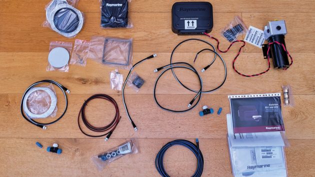
Nearly all the parts you need for installation come with the Raymarine kit, although Gilbert added some longer SeaTalkNG (StNG) cables as well as fuse holders, wire, cable ties and hydraulic hoses. Credit: Gilbert Park
It must also be 2m away from the radar beam and fitted to be level in all directions.
Under the forward bunk seemed the best place to fit the bracket (it can be flush mounted), but it would be difficult to get at the stringer I decided to use for the mounting and it wasn’t vertical.
I therefore, screwed a piece of marine plywood to the stringer so that the heading sensor stayed vertical.
Once dry fitted I took it off again and applied Sikaflex on the back of the plywood and screwed it back into position.
Continues below…
Raymarine ACU-150/ACU-400 Autopilot system recall
Boaters who own a Raymarine ACU-150/ACU-400 Autopilot, which was manufactured between June-July 2022, are being asked to return them due…

How to improve vane steering in tricky wind conditions
Use a tiller pilot

How to replace hydraulic steering hoses and refill the system with fluid
I bought my three-year old Jeanneau Merry Fisher 855 in November. After a full survey I sailed her back to…

How to steer a yacht without a rudder: Jury steering methods tested
How would you cope if your boat lost its steering at sea? PBO tries a variety of jury steering fixes…
The following day I fitted the bracket and heading sensor and connected up the SeaTalkNG (StNG) cable which I took aft to connect to the StNG 5-way connector.
The connections around the helm were next.
I needed to find power for the 5-way connector bar and a place for the steering control head.
The power for the StNG 5-way connector was taken from the fuse board and brought up to the helm position.
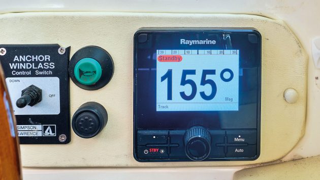
The best place for the control head was the outside of the wheel, where there was a panel. I made a temporary panel with the existing anchor winch control, horn and battery link button moved closer together to allow the fitting of the steering control head.
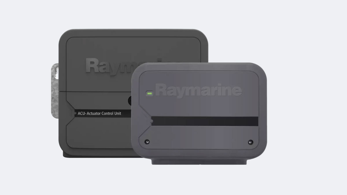
Fitting the ACU
The control box (ACU) had to be fitted near the hydraulic pump, ideally close to the steering cylinder.
In the after compartment there was room to fit the control box to the side of the hull using marine plywood and Sikaflex.
The ACU was screwed to the plywood pad and the cover on the ACU was removed.
Power for the box was taken from an unused 12V accessory socket in one of the removable locker liners.
After that I had to connect the ACU to the StNG network. One of the supplied StNG cables had 5 wires.
The ACU had a removable plug with clearly labelled screw connectors in which the 5 wires were fitted.
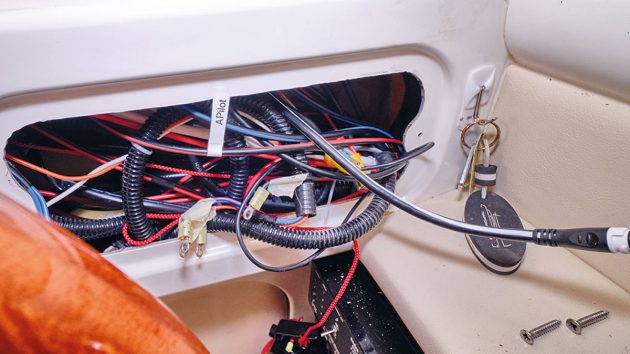
Wiring the SeaTalkNG cable to the power at the helm position. Credit: Gilbert Park
The connector was pushed into its socket and the wires were secured with cable ties to the ACU. The StNG cable going into the ACU was connected with a long cable to the helm position.
Power came out of the ACU to the pump. Once all the wiring was in place the cover was put back.
The hydraulic pump was installed at the bottom of a locker and I decided to use rubber mounts, so I had to get access to the underside via an access panel.
Having got all of the electrics out of the way it was time to move onto the hydraulic connections.
I needed three new hoses. Two to go from the pump to a T-piece on the steering ram and one to go back to the upper steering wheel pump to return fluid from the pump.
The return hose doesn’t have much pressure in it, so can be of a different material (and less expensive).
I measured the length that I needed for each hose and took with me the fittings I had already removed to a specialist hose supplier, who was able to make up the three hoses with the right fittings, those in the stern made of stainless steel and those at the after helm position of normal steel.
The three hoses were expensive, but they fitted perfectly.
Raymarine warns against using PTFE tape or other sealant on the screw threads of the hydraulic pipes.
It is unnecessary and particles may get into the system with the potential to cause valves to jam.
Making connections
The hydraulic return pipe to the steering helm pump was the most difficult part of the installation – the four bolts holding the pump to the bulkhead were difficult to reach for me with my large (and arthritic) hands.
Fortunately, I have a neighbour who helped me out.
Once I’d connected all the hoses it was time to fill and bleed the system with hydraulic oil, as specified by the steering cylinder manufacturer.
Other advice out there is to use automatic transmission fluid, but the instructions for the steering cylinder were very specific about not doing this, except in an emergency and then the system should be emptied as soon as possible and refilled with the recommended oil.
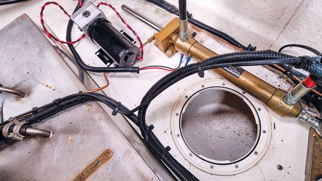
Gilbert decided to site the pump at the bottom of a locker. Credit: Gilbert Park
I bled the system using the nipples on the cylinder, but when the steering was tested, it was clear it hadn’t been fully bled.
Repeated bleeding didn’t solve the problem.
What I had to do was put George into Auto mode, press the -10 button 10 times so the rudder was driven to port and turn the wheel hard to starboard until all the air was out of this side of the pump. Then do the reverse.
This worked and the system was now properly bled. Up to date software
Next, I had to check the installation, starting with ensuring the software was up to date.
As the autopilot was connected to a Raymarine MFD (Multifunction Device) and the boat was next to the house, all I had to do was connect the boat to the house wifi.
The MFD then checked the Raymarine site and updated as necessary.
If you don’t have wifi, you could use a phone hotspot or download any updates onto an SD card before inserting it into the MFD.
I powered up the head and followed the setup wizard, filling in the details of the boat etc.
Next came the Dockside Wizard which checked that the rudder was centred and the rudders moved the correct way.
The way the rudders move depends on how the hydraulic pipes are connected.
If the rudder does turn the wrong way (ie the rudder turns to port rather than the expected starboard) it’s easy to correct electronically at this stage. I went out in the boat to test George and everything seemed to be working.
In particular, the compass was accurate.
There were various other procedures done automatically when the boat was underway that needed no input from me, but should be locked afterwards to stop repeated updating.
The final job was to make a matching, covered panel for the steering head to replace the temporary wooden one. Job done!
Installing a Raymarine autopilot

1. Starting forward, I fitted the heading sensor. This had to be level in all planes but the stringer narrowed towards the top, tipping the sensor up. I fitted a small piece of marine ply to the stringer using screws and Sikaflex to ensure it was upright, then I fitted the bracket to the plywood.

2. The heading sensor is locked into place with the mounting trim, ensuring the longitudinal arrow is in line with the centreline. Then connect to the StNG cabling using a T-connector. Note terminator on the end of the T-connector – one is needed at each end of the backbone (blue/black )StNG cabling.

3. The StNG 5-way connector behind the instrument panel with cables from the heading sensor, the MFD, the control head, the control unit and the. (red/black) power source. The blue/black backbone cable is inserted into the blue sockets and the white/black spur cable inserted in the white sockets.

4. Power for the StNG 5-way connector at the fuse board. A 5A fuse was fitted and labelled for future reference. Note the spare fuse that has been cable-tied to the wire so it’s easy to find in a hurry.

5. To fit the ACU a piece of marine plywood was stuck to the side of the hull in the aft compartment out of the way of the box liners for the starboard deck hatch. The original connections to the starboard side of the steering ram and bleed nipple can be clearly seen.

6. The ACU in position with cabling for the StNG system and power in place. The cable is connected to a T-piece with terminator. Note the four vibration reducing mounts in place ready for the hydraulic pump to be bolted down. The red/black wires coming from it were connected to the ACU ports.

7. Two hydraulic hoses were taken from the pump to the T-pieces at the steering ram. The third was the return which went on to the after steering helm. Being the higher of the two helms any air getting into the system can be easily vented from here.

8. Then it was time to bleed the system. I used a detergent bottle with part of the bottom cut off to allow a refill and air into the bottle. A length of clear tubing was attached to the nipple on the detergent bottle and at the other end the screw fitting at the helm. Paper towels were to catch any spills.

9. The autopilot is connected up. Red tape was put on to the existing hose before disconnection to ensure the hoses were reconnected the correct way around after T-pieces were installed. The pump is seen connected to the ACU as well as the three hoses.
Enjoyed reading Fitting my own Raymarine autopilot? 
A subscription to Practical Boat Owner magazine costs around 40% less than the cover price.
Print and digital editions are available through Magazines Direct – where you can also find the latest deals.
PBO is packed with information to help you get the most from boat ownership – whether sail or power.
-
-
-
- Take your DIY skills to the next level with trusted advice on boat maintenance and repairs
- Impartial in-depth gear reviews
- Practical cruising tips for making the most of your time afloat
-
-