
After finding a hydraulic oil leak in the steering of his Nauticat 331, Mike Corp services the yacht’s helm pump and steering ram
Seeing small amounts of hydraulic fluid below the steering wheel and having to top levels up hinted at a maintenance job for the winter.
However, it wasn’t until we were entering Lymington behind the Isle of Wight ferry that we realised the severity of the hydraulic oil leak.
We had to use the bow thruster to coax the Nauticat 331 out of the line-up so we could anchor and top up the fluid level.
I was sailing with John, a former work colleague, and we returned to our Brixham base.
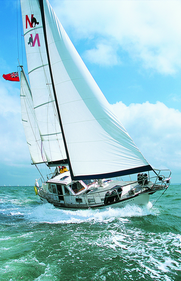
Mike sails a Nauticat 331, similar to this one. Credit: Graham Smook/YM
The near-miss motivated us to change the seals on the upper Capilano helm pump and Capilano steering cylinder, which was also showing some seepage.
The Nauticat is a dual helm boat, and even though the lower helm was free from leaks, we decided to change the seals on the lower helm at the same time.
For someone with little mechanical experience, pulling apart a helm pump and the steering cylinder can seem like a daunting job.
However, if approached carefully, with the occasional image to aid recall, it’s doable and definitely cheaper than contracting the work out.
There are online videos that demonstrate similar jobs being carried out.
Disassembly, inspection, clean
This was probably the first time the pump had been pulled apart since the boat was launched in 2003.
There was a small amount of sludge inside the pump housing and the seven pistons. The ball bearing race and pivot plate were in good condition.
All the parts were cleaned in white spirit, dried, and reassembled with hydraulic fluid.
The recommended fluid is either Dextron 2 or Dextron 3.
Although not shown in the step by step, the rear plate was removed, and the flat bearings were cleaned and replaced with a new gasket.
We never succeeded in removing the two pressure relief valve screws.
The valves worked, there was no leakage and we risked damaging their heads if we persisted with their removal.
Reassembly issues
The seal kit includes seals and O-rings for several models, so it’s important to match your old seals against those in the new kit.
Care is required when fitting the front plate to avoid trapping the new O-ring against the pump housing.
It’s made more difficult because the seven piston springs were resisting our attempts to evenly refit the plate.
After various attempts, we saturated the area in hydraulic fluid and slowly screwed the plate down using longer bolts, which bridged the gap between the plate and housing.
The correct bolts were then inserted and tightened in a criss-cross pattern.
The final job is fitting the seal plate over the seal. It’s a tight press fit and requires a tag to be inserted into a recess.
A simple tap with a hammer and block didn’t work, and we eventually chamfered the leading edge of the plate to facilitate the fit.
Servicing the steering ram
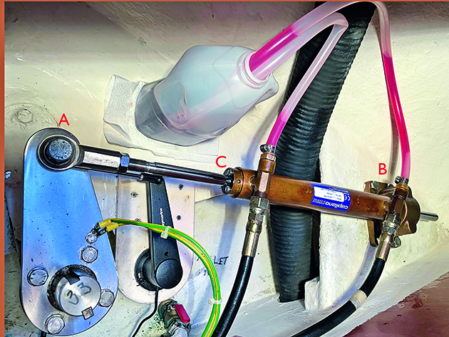
The cylinder is ready to pump out hydraulic fluid. The ball joint (A) and foot (B) are disconnected. A leak was seen from the moulded end cap (C). Credit: Mike Corp
A small amount of fluid was found below the steering cylinder (at C, above), and we decided to press ahead to bring all the hydraulics up to spec.
There is a little more work involved when disassembling and replacing cylinder seals – the cylinder seal pack includes four pages of diagrams and instructions.
Disassemble
The two supply pipes are disconnected and covered to prevent contamination. Before we can access the seals, two hose fittings, the mounting foot (B, above), and the rod end ball joint (A, above) were removed.
The threads on the hose fittings and cylinder access holes were clogged with sealant and needed particular attention.
Carefully placing the cylinder in a vice, we removed the two end glands.
At the ball-end joint, the hose fittings are unscrewed to start removing the retaining ring and gland. The procedure is the same at the foot end. Credit: Mike Corp
A couple of C-spanners were obtained via ebay, though the guidelines recommend using a pin wrench.
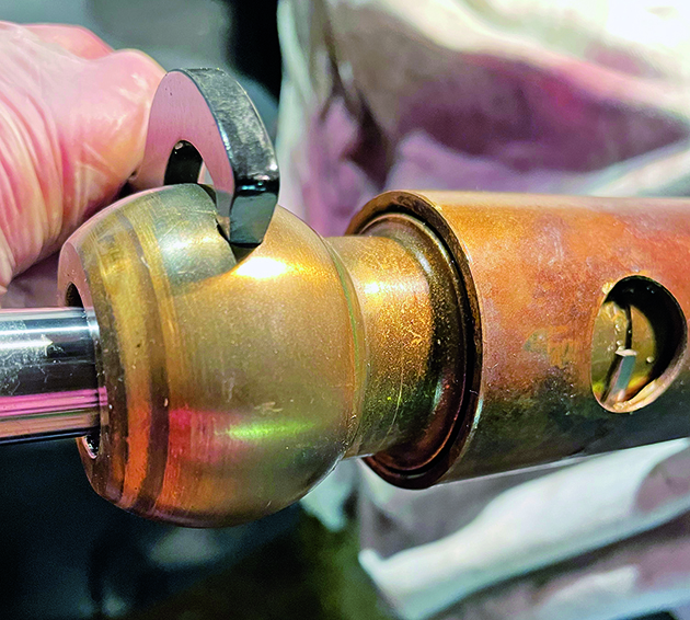
As the C-spanner tip was slightly larger than the gland access hole, we ground it down to the correct size. Rotating the gland anticlockwise, the retaining ring appears.
We bent the leading edge with a screwdriver so that it protruded above the cylinder and could be extracted with pliers while continuing to turn the C-spanner.
It is the same procedure at the other end of the cylinder. Both glands were removed and the cylinder shaft pulled out.
Inspect, clean, and reassemble
For a piece of equipment that is working continuously, the cylinder internals were in very good condition.
If we’d experienced difficulty removing the glands, and especially the cylinder shaft, it may have hinted at damage within the cylinder requiring a major purchase.
Fortunately, the cylinder was free of scratches and dents, so we moved on.
Old seals were removed; everything was cleaned and lightly covered in hydraulic fluid.
A C-spanner is rotated anticlockwise until the retaining ring appears. Continue turning the C-spanner and inserting a small screwdriver to bend the tip outward. It’s then possible to grip the ring with needle nose pliers while turning the spanner. Credit: Mike Corp
Two new U-cup seals were lubricated and fitted to the cylinder shaft with the open side of the seal pointing away from the centre of the shaft.
While inserting the shaft back into the cylinder, we carefully guided the cup seals’ leading edges to prevent them from becoming trapped or cut by the cylinder opening.
Reinserting both glands into the cylinder requires a decent splash of hydraulic fluid and gentle guidance to prevent the cylinder end from cutting the O-rings.
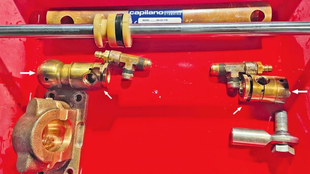
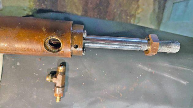
With both glands extracted, the cylinder shaft is drawn out. Items are laid out in their respective assembled positions. The shaft has the left U-cap seal removed. White arrows indicate the location of the seals. Credit: Mike Corp
The supplied kit includes two greased steel retaining rings for locking the glands in the cylinder.
The hose fittings are inserted when the hole in the gland is lined up with the threaded cylinder hole.
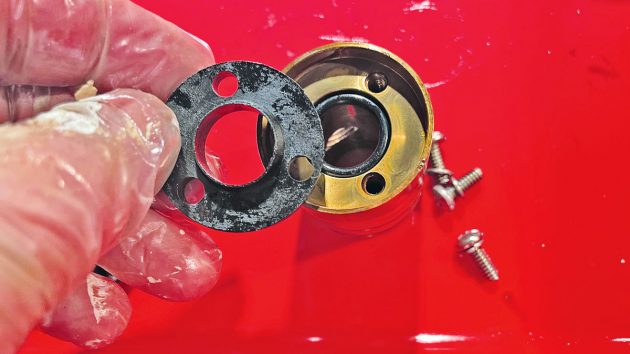
The rod end O-ring is held in place with a moulded end cap and three screws. On the opposite ball end, there is a similar arrangement with an O-ring and press-fit wiper ring, not shown. Credit: Mike Corp
We used Loctite 542 thread sealant, which is recommended for medium-pressure hydraulic systems.
The sealant was left for 24 hours to cure before bleeding air out of the system.
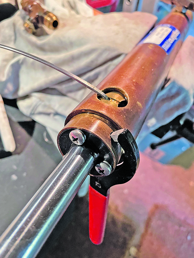
The greased retaining ring is inserted into a guide hole and drawn into the gland as the C-spanner is turned in a clockwise direction. The hole that accepts the hose fittings is just visible and will reappear when a full turn is complete. Credit: Mike Corp
Bleeding air from the system
Bleeding the system requires two people.
One at the top helm, filling the reservoir to maintain the hydraulic fluid level and turning the steering wheel, and a further operator at the cylinder end to monitor the output and close bleed nipples.
At times, it would have helped to have had a third person particularly when bleeding the lower helm. We decided to flush out all the old fluid and replace it with new.
Air has to be removed from four units: the two helm pumps, the cylinder, and the autopilot.
Procedure for purging the system
The guidance that accompanied the 2003-installed Capilano system recommended starting at the top-most helm, moving to the lower helm and, when complete, bleeding air out of the autopilot.
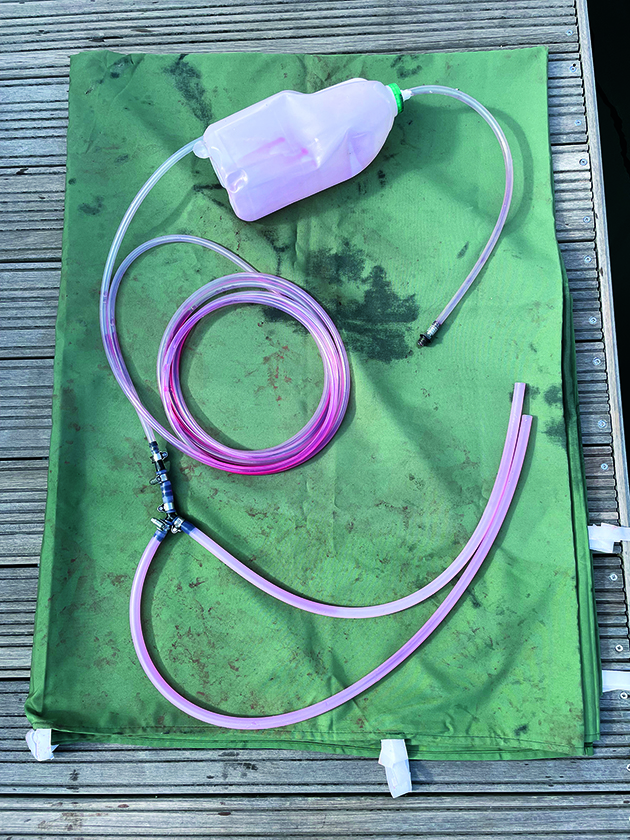
All the parts for the bleeding operation were laid out. The milk container has a silicone tube glued into the lid and a hole in the bottom for the return flow from the cylinder. Credit: Mike Corp
If you have never purged a system before, you may be puzzled by the 2003 version’s guidance as there are some minor omissions that may confuse someone.
Fortunately, there is a lot of helpful information on the internet.
- Fit bleed tubes on the two cylinder nipples and clip them on. Use a large container for any expelled fluid.
- Open both cylinder bleed nipples.
- The upper helm is also the reservoir for the hydraulic steering system. While purging the system, it’s important to ensure fluid levels are maintained. Turning the helm wheel slowly while bleeding is probably safer as it allows oil to fill vacant areas and prevents air from being drawn into the helm when fluid levels are low.
- Turn the upper helm wheel to starboard and when there is a steady bubble-free flow of oil, slowly turn the upper helm wheel to port.
- When satisfied that air is expelled from the upper helm, repeat the procedure at the lower helm.
- Close both bleed nipples.
- Finally, check there is no remaining air by forcing the upper helm wheel hard over to starboard and holding for a minute observing the fluid level. Then turn the wheel to port holding for a minute. Repeat this task between six to 10 times while monitoring the fluid reservoir level. Repeat the above task at the lower helm.
If all air has been successfully expelled, holding the wheel hard over should not lead to a significant drop in oil at the reservoir.
But, if the level varies or bubbles appear in the reservoir, it may be necessary to rebleed the system.
Bleeding the autopilot
The autopilot is considered a steering station and in the Nauticat 331 it is set lower than the inner (lower) helm position, so it is last in the sequence of units to bleed.
We switched on the pump, and while in auto mode:
- Set the pilot to turn 100° to starboard while holding the steering wheel hard over to port, which forces air out through the reservoir.
- Repeat for the port side setting the pilot to 100° to port while holding the wheel to starboard.
We repeated this until we were confident that all air had been removed. John and I spent hours bleeding the dual helm system; it was surprising how much air appeared long after we believed we’d cracked it.
A method for bleeding single-handed
There is a method for one person to bleed a system, which we found on YouTube. We set up a similar arrangement to try it out.
For this job you’ll need: n Sufficient silicone tubing to reach from the reservoir to the cylinder.
- A barbed Y-connector to accept the silicone tubing and connect to the two cylinder bleed nipples.
- For the Nauticat 331, a ¼in BSP straight threaded male connector with a barbed tail connector suitable to accept the silicone tubing.
- Clean 2lt oil container with a short piece of tubing glued into the lid and an opening in the bottom for oil.
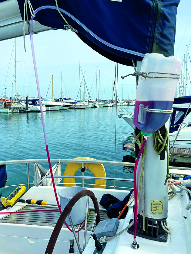
Silicone tubing is attached to both nipples on the cylinder and joined to the Y-connector. This is led up to the oil filler container to feed the upper helm.
Hydraulic oil is added to the container and both nipples are opened one and a quarter turns.
Continues below…

How to service a marine diesel engine in 12 simple steps
It was time to service the marine diesel engine on our Maxi 84 cruiser. Knowing how to diagnose and fix…

How to replace hydraulic steering hoses and refill the system with fluid
I bought my three-year old Jeanneau Merry Fisher 855 in November. After a full survey I sailed her back to…
How to: Service a winch
A backwinding winch can be extremely dangerous and cause serious injury, so winches should be serviced every year in order…

Replacing a saildrive gaiter: step by step
After seven years of regular use, a saildrive gaiter should be changed before it deteriorates to let water through the…
We slowly turned the upper helm wheel in one direction, observing the flow of oil rising from the cylinder for air bubbles.
When we were sure there was no more air in the fluid, we turned the wheel in the opposite direction until the flow of oil into the container was free of air.
We then moved to the lower helm.
Some general points when servicing a hydraulic steering helm
The task of removing the helm(s) and cylinder, dismantling, cleaning, and replacing seals is time-consuming, particularly if it’s your first time doing such a job.
Taking images of the various stages assists later when rebuilding the units. We also took our time and tried to keep units clean and covered from dust.
When working on the cylinder, we’d recommend marking the threads on the ball-end joint before removing the unit.
We didn’t and had to recalibrate the pilot with the rudder arm.
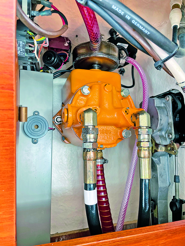
The red hydraulic fluid can be seen moving toward the container and with transparent tubing, it is easy to check for air bubbles. Credit: Mike Corp
Bleeding air out of the system took a long time to complete, longer than changing the unit seals.
We’d leave the boat overnight, believing we’d successfully completed the task, but on returning found that fluid levels had fallen indicating air remained in the system.
The manual advised that bleeding should start at the upper helm, in a dual helm boat, finishing at the lower helm.
But we have seen other manuals suggesting you bleed the lowest helm first and work up.
- It definitely helps to have coloured hydraulic oil as it’s easier to see the movement of oil and any air.
- Locking tubing onto nipples and the Y-connector with hose clips is essential to prevent leaks. We didn’t do this initially and had a bit of a clean-up to do.
- Having a container of fluid suspended above the upper helm reservoir has one major advantage – there is always a source of additional oil at the reservoir, thereby preventing accidentally pulling air into the upper helm.
Once we had acquired the silicone tubing, and the Y-connector and modified the container for draining fluid into the upper helm, the single-handed approach turned out to be very successful. I’d definitely use this method in the future.
Capilano units are from the USA and Canada and use non-metric sizes for fittings, whereas the Nauticat (Finland) employs metric sizes.
We therefore needed to source some AF spanners and sockets for jobs on the units.
The manual describes using ¼in NPT threads for the fluid reservoir filler but the extension fitted by Nauticat requires a ¼in BSP fitting for the upper helm reservoir.
Doing the work yourself ensures a significant saving. The cost of three seal kits was about £180 for two helms and a cylinder.
In 2022, we were quoted £550 for repairs to one Capilano HH5275 helm and one BA150 cylinder. This did not include return shipping (if required) or VAT. Also, there is a ‘materials surcharge’ added by the USA/Canada supplier.
The helm seal kit part number for the Capilano 1250v pump is HS5161 and cost £45.57 plus VAT in 2022.
The kit includes various seals and a diagram of the pump, but no instructions other than the statement that the kit is for an ‘authorised repair centre only’.
The cylinder seal kit part number for the Capilano Cylinder 150-7TR is HS5182 and cost £61.75 plus VAT in 2022.
Both kits can be acquired from Hypro Marine, hypromarine.com.
Helm disassembly, inspection & reassembly: step by step
Credit: Mike Corp
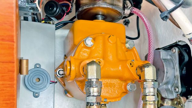
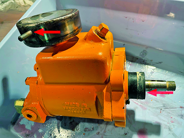
1. A puller is required to remove the steering wheel from the pump shaft. Two high-pressure pipes and three low-pressure pipes were removed at the back. The starboard high-pressure pipe is marked with white tape to ensure correct relocation. The pump is secured to the bulkhead with just two bolts.
Credit: Mike Corp
2. Although it was hard to see, the helm was leaking from the reservoir overflow tube (top left), where a weld appeared to be compromised. There was a leak from the front cover seal plate cap and O-ring (right). The pump was dismantled so that the unit could be sent for a weld repair to the overflow tube.
Credit: Mike Corp
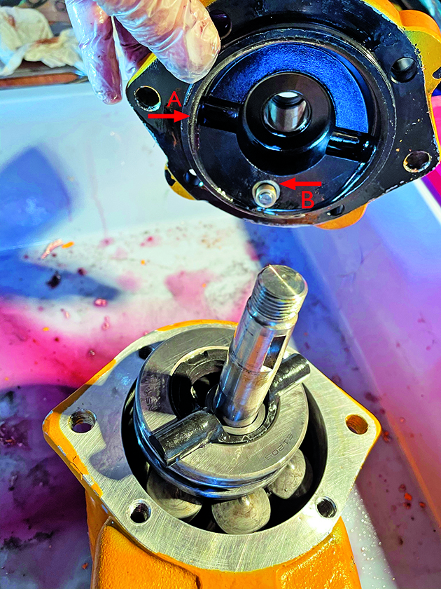
3. Removing the front cover reveals two seals and the pivot plate on top of the pistons. On the inner side, there is a large O-ring (marked A on the photo) and a smaller O-ring (B) around the steering adjustment knob that protrudes into the pump arrangement.

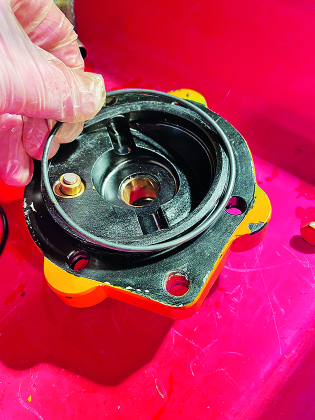
4. There is a third seal on the outer side of the front panel, which is concealed behind a seal plate now removed. The adjustment knob is held in place with a pin and washer and accessed by screwing the knob inwards to remove the knob and O-ring (B in image 3, above).
Credit: Mike Corp
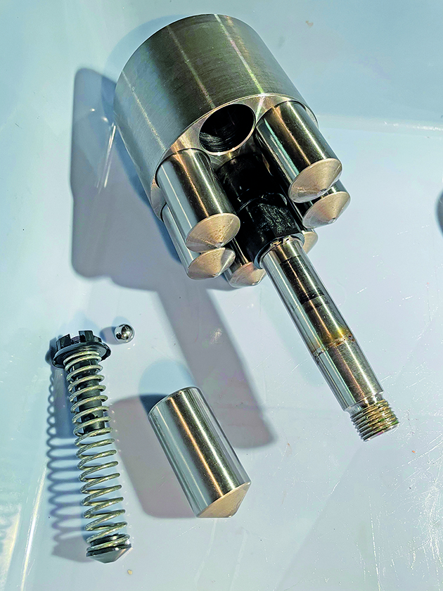
5. We removed the pivot plate, ball bearing race, and main piston arrangement. It’s definitely a good idea to do this job inside a deep tray in case the springs and ball bearings fly out. There are seven pistons, each with a spring, and a small ball bearing held within a plastic cage. There was only mild evidence of wear to the pistons.
Credit: Mike Corp
6. The large O-ring is a tight fit when assembling the front cover. It may help to reduce some pressure from the piston springs by unwinding the small adjustment knob.
Credit: Mike Corp
7. Fitting the new seal plate was tricky. Laying it flat on the front cover and tapping with a block was unsuccessful, so I created a slight chamfer on the leading edge.
Enjoyed reading Servicing a hydraulic steering helm on a boat? 
A subscription to Practical Boat Owner magazine costs around 40% less than the cover price.
Print and digital editions are available through Magazines Direct – where you can also find the latest deals.
PBO is packed with information to help you get the most from boat ownership – whether sail or power.
-
-
-
- Take your DIY skills to the next level with trusted advice on boat maintenance and repairs
- Impartial in-depth gear reviews
- Practical cruising tips for making the most of your time afloat
-
-
Follow us on Facebook, Instagram, TikTok and Twitter