
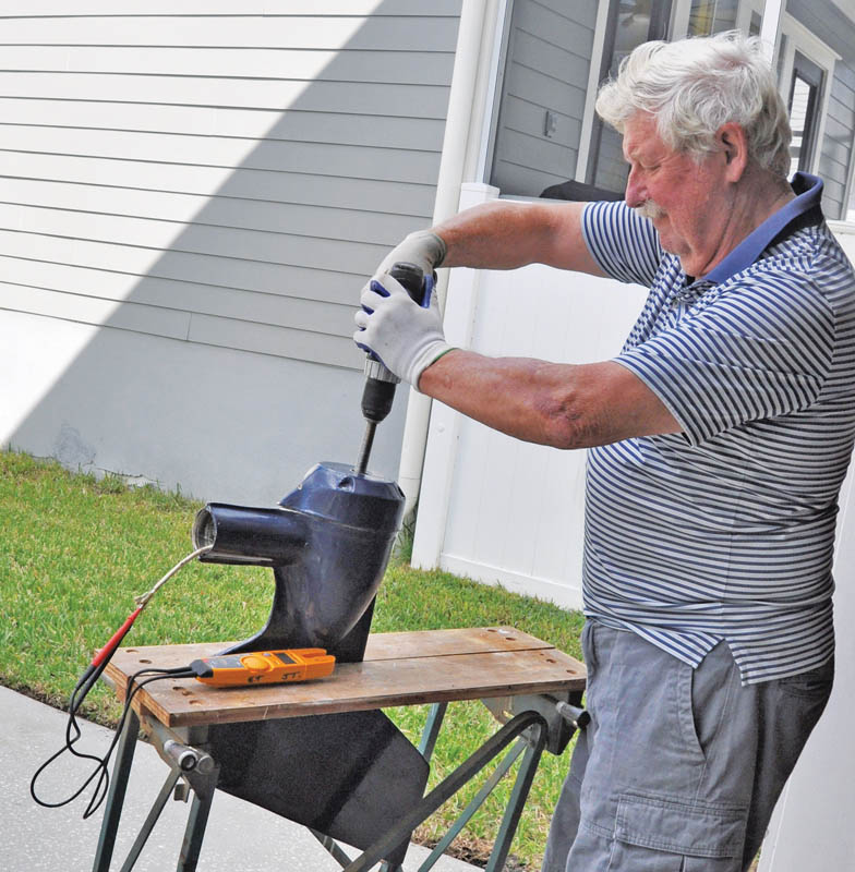
Roger Hughes dismantles and repairs his seized wind generator in the workshop at home after a brush with hurricane-force winds

I confess, I’m frequently guilty of surrendering to the old adage, ‘If it ain’t broke, don’t fix it!’ But I got caught out in hurricane Dorian in October last year. Scheduled maintenance is one thing, but shinning up a 17m (57ft) mast just because a hurricane is expected is another.

However, my laziness meant I consequently had to dismantle and restore my Kiss wind generator – though I also installed a few slight improvements at the time to make regular maintenance easier in the future.
The Kiss is a big, heavy wind turbine that has been around for 21 years and can still be seen churning out electricity in nearly every marina in the world. It had worked flawlessly for the ten years I have owned my 45ft schooner Britannia, and goodness knows how many years before that.
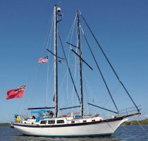
Britannia is a 45ft schooner with a squaresail for downwind legs. She is based in Florida.
When I modified the rig (PBO August 2017) I mounted it high up my main mast for two reasons: to escape the noise of the spinning blades and to improve efficiency (there’s usually more wind aloft). The downside is that it was rarely even inspected, let alone maintained.
Then along came Dorian, one of the most powerful hurricanes recorded in the Atlantic Ocean, rolling up the Florida eastern seaboard in October 2019. It had weakened after devastating the Bahamas and veered away from the mainland, but 100mph gusts were recorded at Cape Canaveral – only a few miles from my pontoon – which is enough to send any wind generator into orbit.
I completely stripped Britannia in preparation for the arrival of Dorian, but I forgot about the lonely old Kiss high up the mast…
When I returned to the boat a few days after the hurricane had continued north on its destructive path, I noticed the genny’ was not spinning, even though there was a 15-knot breeze. Something was up, and it looked like it would probably be me – up the mast to investigate.
Even though there are steps all the way up both masts, I still find it nerve-wracking to scale Britannia’s 57ft main.
As I slowly climb, with the bosun’s chair strapped to my waist, my wife tails the halyard round a winch. When I got up there I found the blades could hardly be turned by hand, and definitely felt like the bearings had seized.
I set up a pulley on the triatic stay with a short length of line, so the pulley was directly above the generator. Then I tied a rope strop round the Kiss body to keep it level so it could be pulled out of its vertical support post. The oval shape of the Kiss body is definitely not conducive to tying a rope strop to it, when swinging 50ft above the deck on a rope. The support post also stands 84cm (33in) away from the mast, so the blades can clear as they rotate.
While I was doing all this I thought: “There has to be a better way than this”.
The machine was finally lowered and I lugged it home, to investigate in my air conditioned workshop.
‘Lugged’ is the operative word, because the thing weighs as much as a car battery, and the blades are around 1.5m (5ft) in diameter.
Stripping down a Kiss wind generator
I should mention here, I’d never dismantled a wind generator before, but I learned a lot about how to do it from the internet.
Top tip
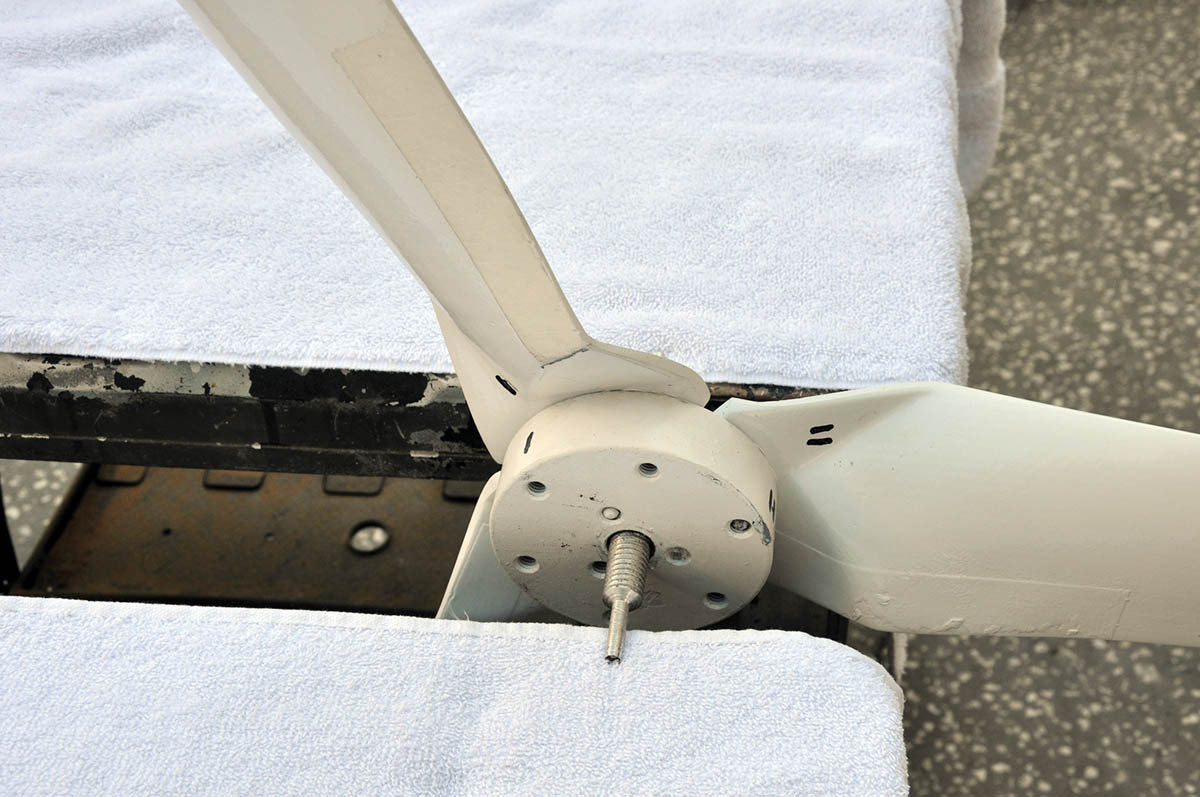
Number the position of the blades when you dismantle. If the blades are reassembled in a different order the whole set-up will need rebalancing
I first removed the plastic nose cone. This just screws on the tapered threaded shaft, but as I unscrewed it the cone broke away from its base – something to repair later.
Next, the nine bolts holding the three blades to the hub were removed. The hub was then unscrewed by holding the shaft with a vice grip and unscrewing it.
Four 14cm (5½in) long screws hold the front casing to the fibreglass body and I was surprised to find they all came out easily, even the last one – which is usually the one which refuses, isn’t it?
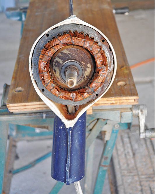
The inside workings look much like an alternator.
I then cut out the caulking sealing the front casing to the body, and after a bit of leverage with a couple of screwdrivers the cover was removed, revealing the inside workings. It looked like a fancy alternator to me, which is more or less what it is.
The outside copper windings are the stator and the rotating bit in the middle is the rotor. The rotor is a very powerful cylindrical magnet, which when spun by the wind, creates an electrical charge in the windings of the stator.
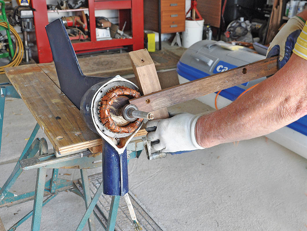
The best way to get the stator and rotor out of the fibreglass body is to lever it out with a stout wooden lever and a block
The next question was: how to get this lot out of the body? I learned from web videos that it was not held in by anything after the four long screws had been removed.
I held the body securely in my bench vice and levered the whole lot out using a piece of wood as a fulcrum.
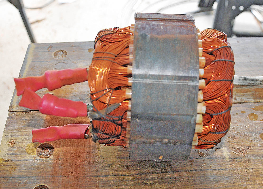
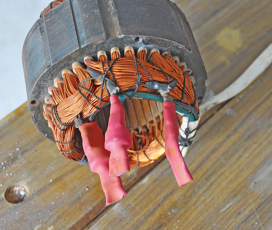
The stator is very heavy, due to many yards of copper wire
The stator and rotor came out in one heavy lump, along with the rear bearing.
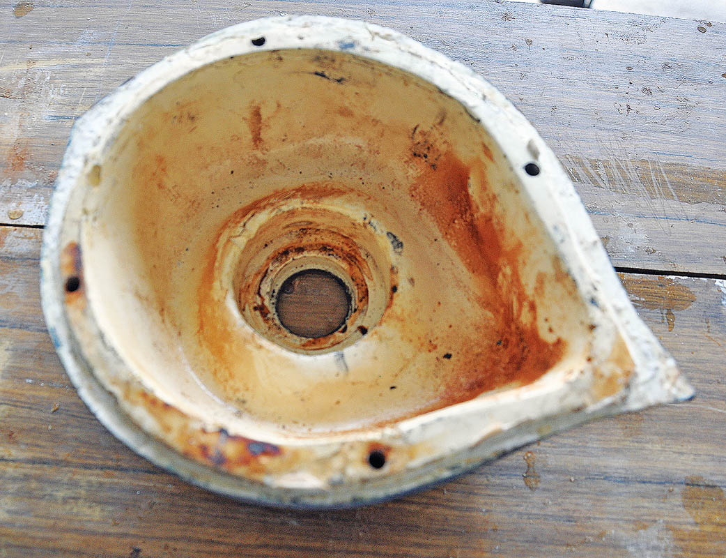
I was then amazed how light the main fibreglass body is. All the weight is in the stator and rotor, so it is best not to let these drop on your toes, because they might become irreparably damaged and you might also need new toes.
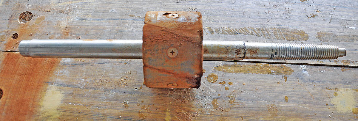
The rotor is a strong magnet which is difficult to withdraw and replace inside the stator
The front bearing had seized and the rear one looked like it was about to go the same way.
I pulled them both off the shaft using a hub puller I’d bought from an auto parts shop years ago, and finally put to use.
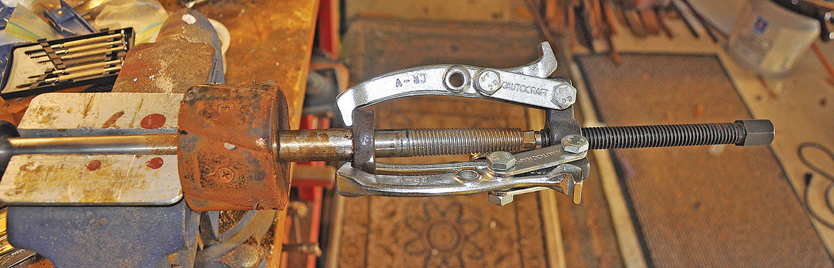
Bearings are best removed with a hub puller, which won’t damage the bearing or the shaft
In the rear of the stator are the thermostats, which prevent overheating and allow the blades to free-wheel in high winds. I tested them with an ohm meter and they all read zero (0.00), meaning they were likely still working fine.
It was then just a question of cleaning everything and buying new bearings and bearing seats.
The thermostats control the opening and closing of the electrical circuits
One of the advantages of the Kiss generator is that bearings and seals are available more or less anywhere. I ordered mine from Amazon at only $5 each.
Repair and reassembly
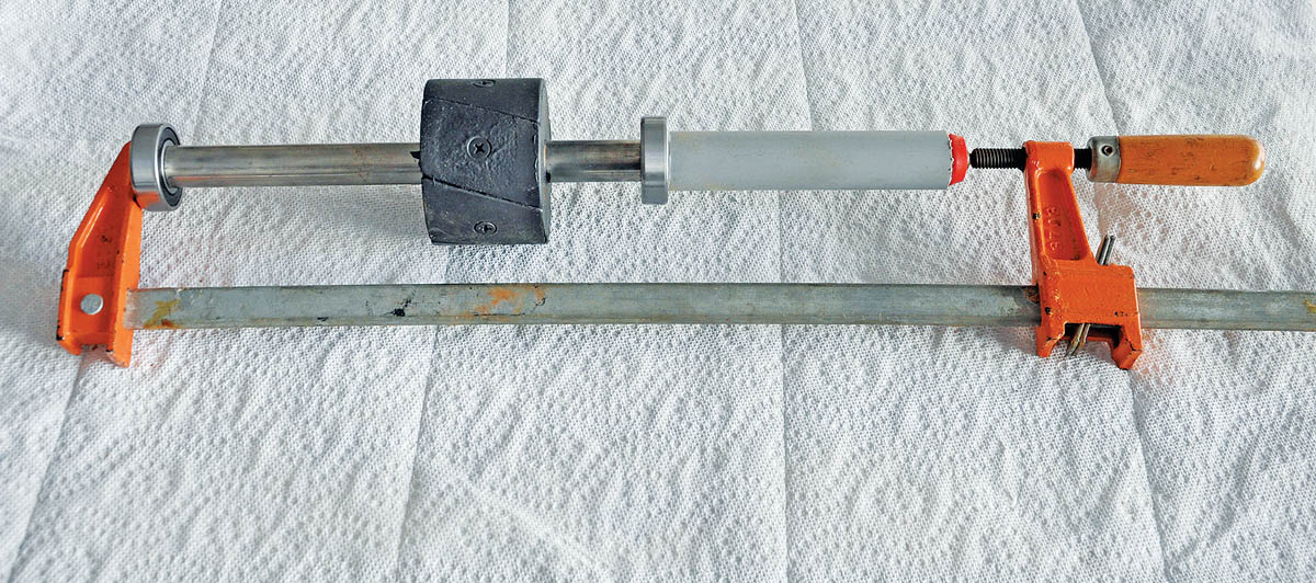
New bearings can be pushed on the shaft using a bar clamp and some plastic tube
I pressed a new front bearing onto the rotor shaft using a bar clamp and a 19mm (3⁄4in) inside diameter plastic tube. I used the same clamp and a block of wood to locate the rear bearing, both bottomed against lips on the shaft.
The rubber bearing seats centralise the bearings in their housings, and the rear one needed to be fitted before the stator was replaced.
Before finally replacing the stator and rotor I decided to install an improved hoisting point, so I wouldn’t have to set up that clumsy rope strop again.
I first found the exact horizontal balance point of the assembled machine with the blades attached, which is – as one might expect – the vertical axis of the swivel pipe.
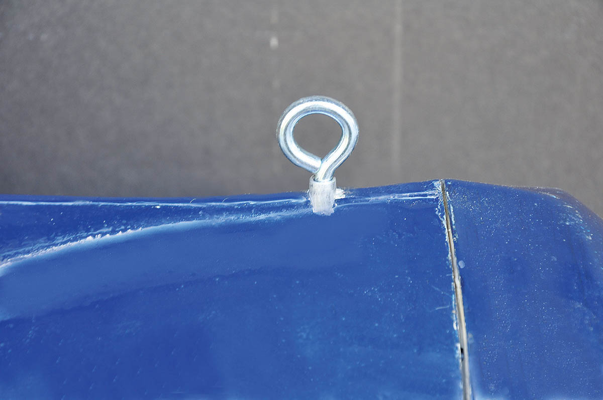
Installing this eye bolt made it much easier to hoist the Kiss back up the mast and drop it into the mast bracket
I then drilled an 8mm (5⁄16in) hole through the top of the body on this axis and pressed an aluminium threaded insert through the hole from the inside.
This has a small shoulder which prevents it being pulled through by the weight of the Kiss.
I sealed round the insert with epoxy, then screwed a stainless steel eye bolt into the insert, after sealing the threads with a few turns of PTFE tape. The Kiss now hangs perfectly level from this eye bolt.
The stator was then carefully lined up with the holes for the four screws, and pushed into the casing.
The rotor then has to be re-inserted inside the stator – carefully, and wearing industrial gloves.
Because of the magnetism it is hard to push into the windings – until it suddenly decides to let go and disappears into the winding, hopefully not with one of your fingers.
Before replacing the front cover a new front seal was pushed in along with a new bearing seating
The front cover has a small dust and water seal in the front, which should be replaced before the cover is bolted back on the body. The old seal is easy to push out and a new one pressed in.
A bearing seating was also inserted in the front cover recess. I masked all round the joint with tape, then caulked it with 3M 4000, then tightened the front cover to produce a watertight seal.
I forgot to number the position of the blades on the hub before removing them (hence the Top Tip earlier in the article), so it was necessary to rebalance them to ensure a vibration free rotation with minimal wind noise. If I’d marked them beforehand this would have been unnecessary.
Balancing the blades is a necessary final operation to ensure smooth rotation of the blades to reduce noise and vibration
Balancing is done using a tapered mandrel through the hole in the hub, supported between two level benches.
In an unbalanced assembly the heaviest blade always rotates to the bottom, I then shaved off a little piece of the lead tape which is glued to the back of that blade. This was repeated until the assembly rotated freely and stopped in any position.
After reassembly the generator was tested by spinning the shaft with an electric drill and measuring the output on a multimeter
Before replacing the blades I tested the Kiss by connecting the output wires to a multimeter, then spun the shaft with an electric drill to simulate the wind rotation. The output was up to 28A AC.
I also made a stronger repair to the two plastic nose cone pieces, by pop-riveting them with four tiny rivets. This completed the reassembly of the actual generator.
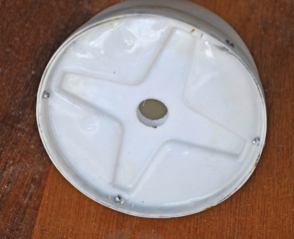
The nose cone and base were pop-riveted together to prevent them separating at high revolutions
Reinstalling the Kiss wind generator
Hoisting the machine up the mast was made very much easier by tying a snap-shackle to the hoisting halyard and hooking it through the eye bolt, whereupon the machine sat perfectly level. It was then just a matter of guiding the wires and the Mercotac switch through the support bracket tube, lowering the machine and reconnecting the wires that go down the mast.
What is a Mercotac switch?
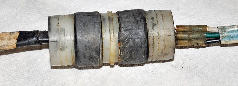
Mercotac wire connector maintains connectivity through 360°
A wind generator needs to be able to freely rotate in any direction to face into the wind, and the wiring for the Kiss has a Mercotac-type connector which can rotate through 360° while maintaining connectivity without the wiring becoming hopelessly twisted. This connector is even more vital in high, unpredictable winds when a generator mounted high up a mast can’t be easily restrained using a rope tether, like those which are mounted on a pole aft can be.
Back on deck I used a multimeter to test the six one-way diodes on the rectifier in the control box. These convert the AC output of the generator to DC for the batteries, and they were all reading correctly. I replaced the control box behind the main electrical distribution panel in the saloon.
I switched the Kiss on, and even though there was only 5 knots of wind the blades were soon whizzing round, with 6A DC showing on the meter.
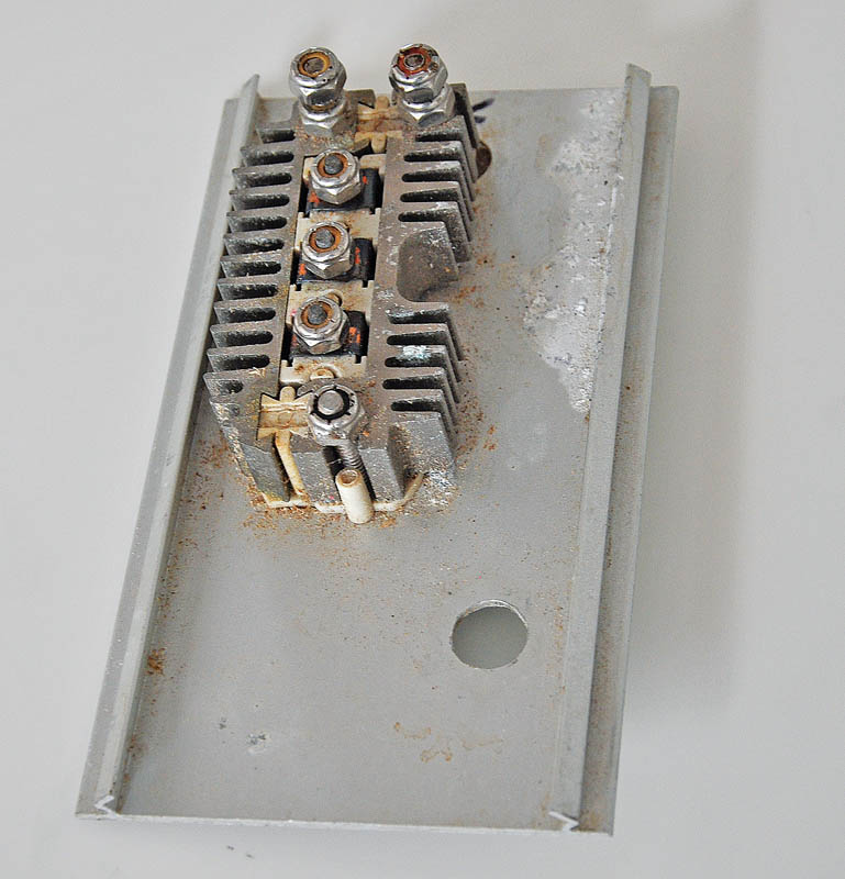
The control box contains six diodes and a heat sink, and converts the AC output into DC for the batteries
In hindsight it would have been much less effort to have gone up the mast before the storm arrived and simply unscrewed the hub with the blades attached. A halyard simply tied to a blade would have lowered it.
The actual machine could then have stayed where it was – without blades the generator wouldn’t spin – the bearings would not have been damaged, and a lot of work would have been saved.
Originally published in PBO Apr 20.