
David Berry demonstrates the simple DIY electronic repairs required to rescue some legacy electronics - Autohelm ST4000 and Garmin GPS 152

You don’t always need oscilloscopes, signal generators or even voltmeters to find faults in your boat’s instruments and effect decent DIY electronic repairs. So long as you have a magnifying glass, problems can often be detected just by careful examination and then fixed with a soldering iron.
There’s no magic involved, and – with one proviso – it’s always worth taking the back off an instrument and having a look.
14 simple boat electronics repair tips and tricks for boat owners
The proviso is that you should never try this kind of open-heart surgery unless you are convinced that the instrument you are going to operate on is terminal, is long out of its warranty and is not worth the cost of having an electronics expert have a look at it.
Only try it as a last resort just before you throw the thing away! If in doubt, it might even be worth asking the instrument’s manufacturer. With old or obsolete kit they’re often happy to advise on what might be done.
This article was first published in PBO in 2013! For a more recent electronic repair see: How I fixed NASA Clipper Wind instrument
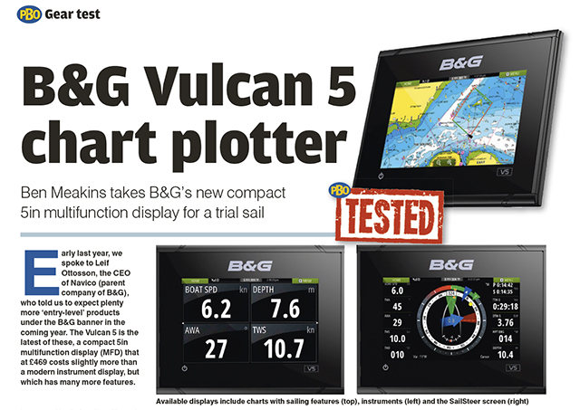
PBO Tested: B&G Vulcan 5 chart plotter
Ben Meakins takes B&G’s new compact 5in multifunction display for a trial sail

Nav in a nutshell: Electronic charts
Dick Everitt assesses the differences between raster and vector charts when deciding on which chart plotter to buy
How I fixed my own Autohelm ST4000
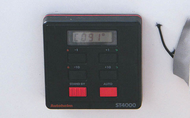
The Autohelm ST4000 had worked well for many years then one day failed without any obvious cause.
Symptoms: Complete failure. I was looking at finding and fitting a replacement.
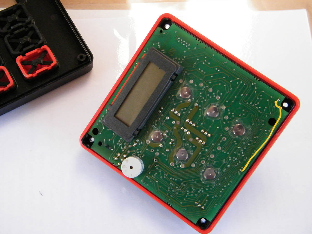
Investigation: The unit is held to the bulkhead by two thumb-wheel nuts and was easily removed. I noted the positions of the wire connections and then unscrewed the four small self-tapping screws and separated the two plastic body shells carefully. There’s a silicone rubber seal between the two shells that keeps the water out.
The front shell comes away, leaving the printed circuit board (PCB) plugged into a ring of contacts on the rear shell. It can be carefully pulled away, giving access to both sides of the board.
I always look for burn marks and damage that might indicate where a component has failed, but could find nothing wrong until I held the circuit up to the light when the gap in the lower tracks became obvious, one on each side of the board.
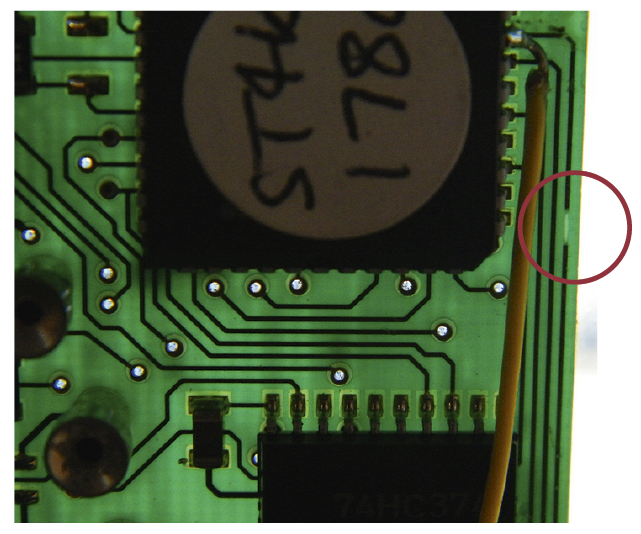
I found the broken track by holding the circuit board up against the light. The tracks show up strongly against the translucent board and the gap is obvious.
Was it caused by a leak? There was no other evidence and I’ll probably never know for sure, but something certainly created the gap in the track.
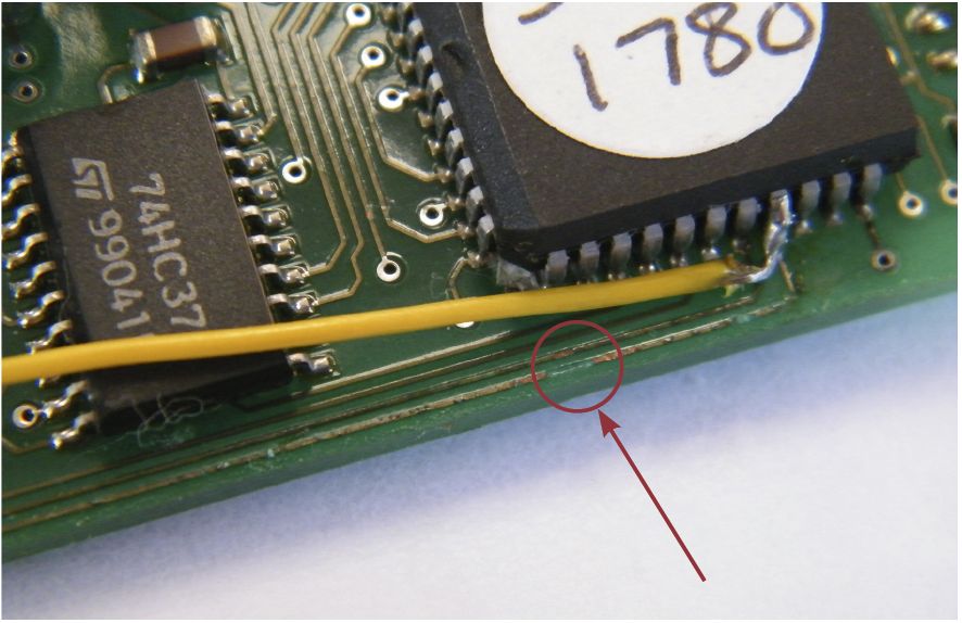
The broken track is evident in this photo, nearest the edge of the board. Because the track itself is so small I chose the leg of the integrated circuit to solder the wire to. The wire simply parallels the broken track bridging over the break. Because everything is on such a small scale the thin wire looks cumbersome here. To prevent any contact with any other circuit component I sprayed the wire with printed circuit board lacquer.
DIY electronic repairs: Easily fixed by tracing the damaged tracks and soldering a fine insulated wire from the start of the damaged track to the end. I chose the comparatively large pads of components to solder to rather than the tiny copper track and used the minimum heat that would do the job (excess heat tends to cause the tracks to delaminate from the underlying board).
The broken tracks occurred on both sides of the board so the front side also had to have a bridging wire added. Reassembly was a reversal of disassembly, with the silicone gasket suitably smeared in petroleum jelly.
Costs and savings: The repair cost a few pence and half an hour. A new unit would have cost upwards of £500 (in 2013) even if I could get one.
How I fixed a Garmin GPS 152

Symptoms: The instrument kept losing satellite connection, but was otherwise fully functional.
Investigation: This seemed like a fault with the antenna since everything else worked fine. However, I couldn’t take the antenna apart as it is an all-glued construction, so opted instead to look at the GPS itself.
I unscrewed four large and eight small screws, carefully pulled the front and back shells apart and unplugged the power cable, which runs from the external connector to a connector on the circuit board.
The coaxial antenna cable runs directly from the BNC socket on the back panel to the board, so I had to unscrew the socket with a small spanner, taking care not to stress the cable itself.
Then I had the circuit board unencumbered by the body shells. After a few minutes of careful probing I found the antenna wire had a broken solder connection, most likely as a result of vibration.
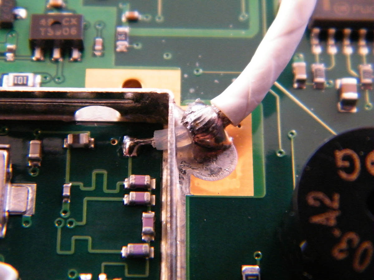
The outer screen of the antenna cable had broken away from the circuit board pad. This caused the intermittent loss of satellite reception I was experiencing.
DIY electronic repairs: I simply soldered it back again. Soldering to the large copper pad took a lot of heat and I was worried that the plastic insulation of the wire would melt before the solder flowed. But as I was otherwise faced with throwing the thing away I took the plunge, used a hot iron and worked very quickly.
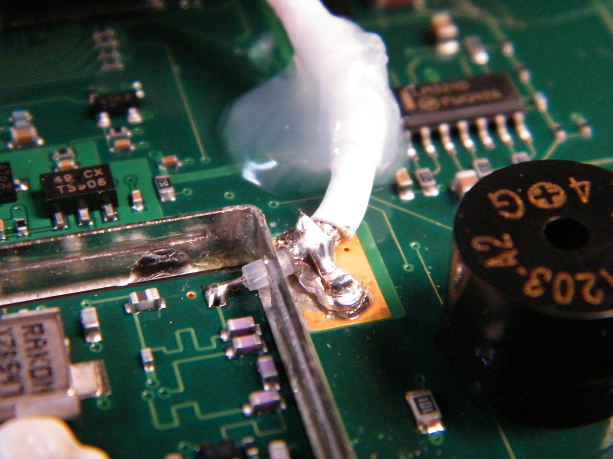
The new shiny solder joint between the outer screen of the RG58 cable and the circuit board pad. The white blob of Maplin silicone adhesive/sealer provides support to the cable.
Costs and savings:
The cost was virtually nothing and the saving was the price of a new Garmin 152, about £200.
Why not subscribe today?
This feature appeared in the Feb13 edition of Practical Boat Owner. For more articles like this, including DIY, money-saving advice, great boat projects, expert tips and ways to improve your boat’s performance, take out a magazine subscription to Britain’s best-selling boating magazine.
Subscribe, or make a gift for someone else, and you’ll always save at least 30% compared to newsstand prices.
See the latest PBO subscription deals on magazinesdirect.com