
Battling with increasingly heavy steering on his yacht led Mike Coates to check out all the possibilities before eventually taking the whole lot apart for a refurbishment. Here he shows how he carried out the job
Over the last couple of seasons, we’d noticed a pronounced stiffening of the wheel steering on our Hans Christian 43T cutter, Jolly Swagman, writes Mike Coates.
The rudder on the Hans Christian is large, like a barn door, and therefore has to have substantial bearings to take the high loads, especially when going astern.
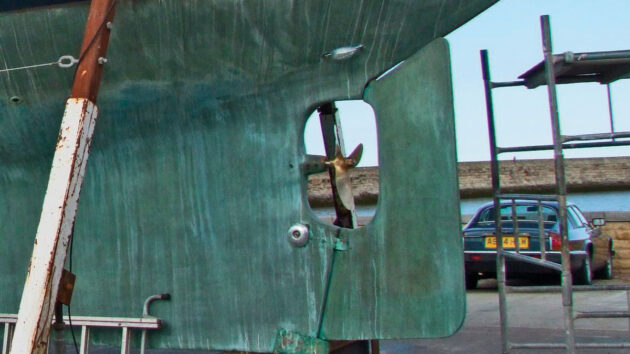
Jolly Swagman has a ‘barn door’ of a rudder: tracing stiffness in her steering proved a protracted job
There could be five main causes of the stiffness: a problem with the underwater rudder bearings, the rudder stock stuffing gland, the linear autopilot drive system, the wheel steering system itself, or the upper self-aligning bearing.
The last three could be addressed with the boat in the water, so I checked those first.
Boat steering: autopilot and wheel
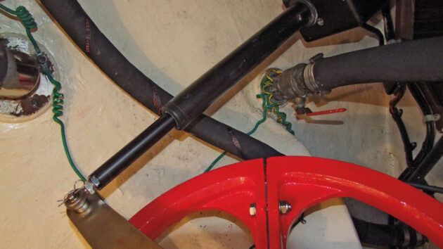
One of the first checks Mike did was to disconnect the autopilot ram from the steering. It proved not to be the problem
I disconnected the autopilot from its separate steering arm on the rudder stock, but as I’d suspected, this made little if any difference to the problem.
Next, I disconnected the steering cable from the quadrant by unscrewing the tensioning eyebolt: this allowed the wheel to be checked for any stiffness, and again this was found to be free.
Upper bearing
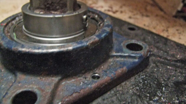
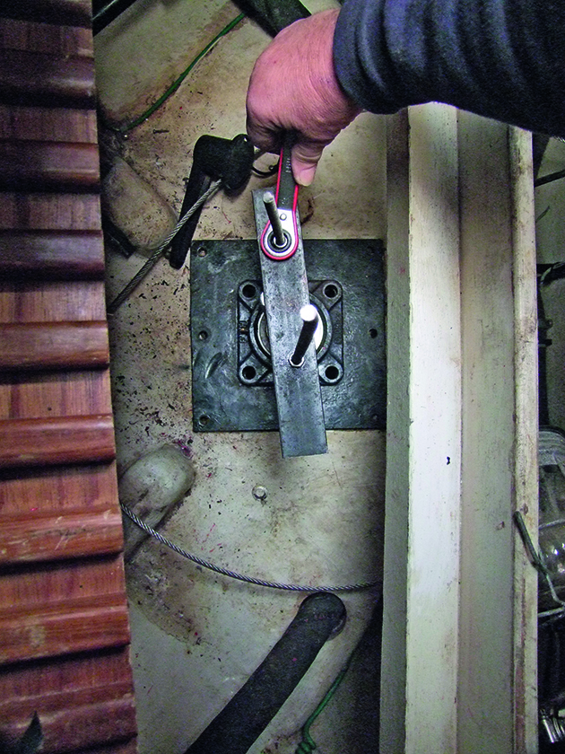
Unbolting the upper bearing allowed it to be spun around the rudder stock. Slight wear was not enough to cause the stiffness
The only other item that could be checked with the boat afloat was the upper self-aligning bearing. It had been replaced five or six years previously, but being a steel bearing (an imperial-sized stainless steel one wasn’t available then), I decided to unbolt it from its mounting so I could rotate it to check for free movement.
The bearing is a complete unit comprising the bearing and a square housing with four fixing holes. Access to the bolts is difficult with the quadrant fitted, but eventually, I removed all four.
When I rotated the bearing, it was slightly notchy, indicating some corrosion to the ball bearings. However, it wasn’t bad enough to cause the underlying stiffness in the steering.
This left two possible causes – the lower rudder bearing or the stuffing gland. As the boat was due to be lifted out for other repairs, I decided to wait until then: access to the stuffing box is limited, and should anything go wrong when dismantling the gland, the boat wouldn’t sink on dry land!
Other bearings which could affect boat steering
Intermediate and lower bearings proved to be moving perfectly freely
As soon as the boat was lifted, I checked the intermediate and lower bearings for signs of sideways movement or wear, but both appeared to be in order.
Stuffing box
The stuffing box gland nuts were next removed. Because of the upper bearing and its associated mounting, I could only partially lift the gland clear to expose the rings of packing material.

The stuffing gland packing seemed dry, but lubrication didn’t solve the problem
With difficulty, I was able to remove three rings of the material, then poured some EP90 high viscosity gear oil into the top of the stuffing box. I replaced the standard flax-type packing I’d removed with a very low-friction PTFE material, then replaced the gland and forced it down into the stuffing box with its adjusting nuts, hopefully forcing the oil through the remaining packing and into the lower bearing of the gland at the same time.
Success: after a few days, I could see oil running down the rudder stock, so I readjusted the gland. The steering appeared significantly easier to use, so I guessed the problem had been a lack of lubrication in the stuffing gland packing.
But with the boat back in the water for a few days, I was disappointed to find the steering had once again stiffened – it would now have to wait until the end of the season before I could do a full strip-down of the system.
Steering quadrant
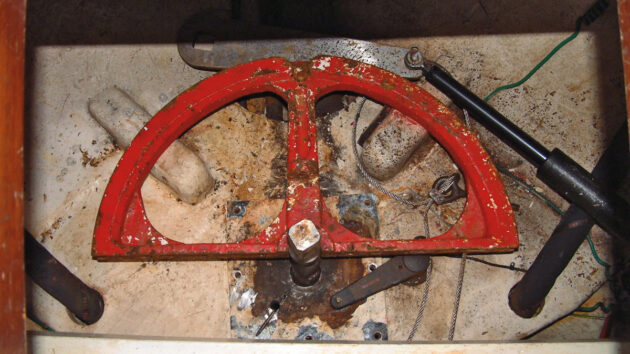
During the winter lay-up, I removed the steering cables and then the quadrant – a heavy item made from cast iron in two parts and bolted around the square of the rudder stock.
Troubleshooting boat steering: Chafing the stops
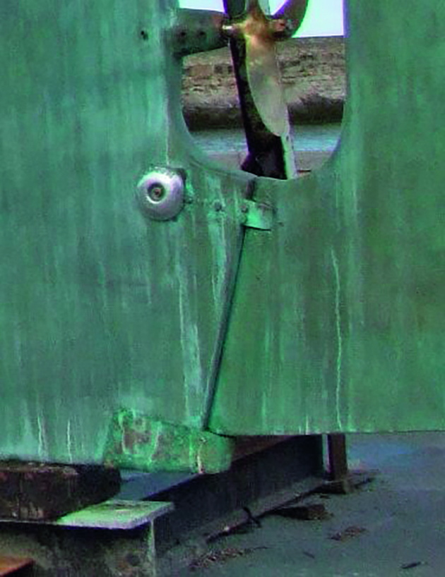
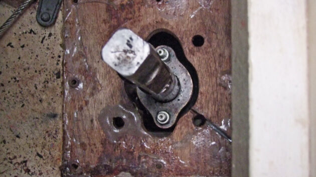
With the steering quadrant removed, the cause of the problem is evident – it has been rubbing on the stops
Once the quadrant was off, the cause of the heavy steering was apparent. Despite the mating faces of the quadrant being bolted tightly together, it had slipped down the rudder stock onto the GRP rudder limiting stops, which are hidden underneath: witness marks on the underside of the quadrant show where it had been chafing.
I can only assume that when the boat was lifted out of the water a slight deformation of the hull when its 23-tonne weight was taken on its keel meant a gap opened up between the quadrant and the stops – that’s why the steering ran free out of the water – but then stiffened again when returned to its normal in-water shape after having been launched for a few days.
While the quadrant was off, I decided to carry out a full overhaul of the boat steering system. I had both joining surfaces of the quadrant skimmed by an engineering company, removing 1.5mm from each face.
This would give tighter clamping of the two halves. The quadrant pieces were then shot-blasted and epoxy-painted.
Bearing replacement
As the steel upper bearing was showing signs of deterioration, I decided I’d look harder for a replacement in stainless steel (the rudder stock being 1¾in (44.45mm) diameter).
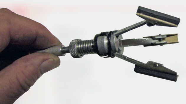
When Mike first replaced the bearing some time ago, he drilled and tapped two holes into the new bearing body. These would allow him to use a puller to help remove the bearing in future
The last time I replaced the bearing, I’d had trouble removing the old one – I’d had to resort to cutting it off the shaft using an angle grinder with a slitting disk. To avoid the same thing happening again, I had drilled and tapped two 8mm holes in the base before installing the bearing.
Puller system
This simple puller helped remove the old upper bearing… eventually
My forethought paid off, as these holes allowed me to use a simple puller made from two lengths of 8mm threaded rod and some 10mm flat bar to bear down on top of the rudder stock and pull the bearing housing up. Despite the puller and liberal amounts of lubricant, however, it still took me more than two hours to shift it…
Mounting plate
Removal of the bearing mounting plate reveals the top of the stuffing gland
The bearing mounting plate was next to come off, exposing the aperture in the ply shelf through which the stuffing gland could be removed.
Stuffing gland
The top of the gland was easily removed, but owing to the difficult access, I needed a special tool that would reach into the bottom to extract the packing. I made one up – really just a large wood screw welded to the end of a suitable length of 5mm rod with a T-handle.
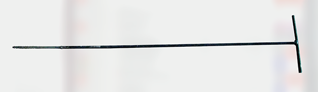
Mike welded a screw to a piece of rod as a tool to reach down into the gland and remove the packing pieces
I screwed this into each ring of gland packing, gradually drawing out all 15 turns of old packing. Using the emergency tiller, I then checked the rudder for free movement before re-packing the gland with PTFE material.
A new mounting plate
Despite a powder coating, the original bearing mounting plate was severely corroded on its underside, so I made a drawing and had a new one cut in stainless steel, at the same time fabricating a set of captive nuts to make it easier to re-bolt the plate and bearing into position.
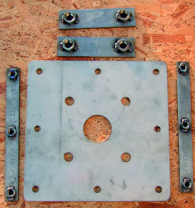
The new bearing mounting plate and captive nuts
Now it was time to think about reassembly, but before I started, I sanded and then cleaned the compartment with acetone to degrease it before ‘flow coating’ with pigmented gel coat.
Finding a bearing
I measured the rudder stock with a digital vernier gauge to ensure it was 1¾in diameter, and to my surprise found it to be 1.772in (44.85mm) dia, .022in (0.4mm) larger than it should have been – the reason the previous bearing had been extremely tight on the shaft.
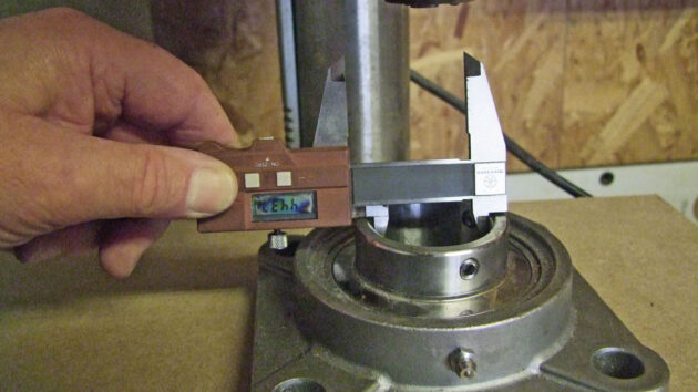
The new stainless steel bearing was too tight a fit on the slightly oversize rudder stock…
I tried the next largest size of bearing, which meant going to a metric size: 45mm onto the stock, but the play was too significant. I eventually sourced a stainless steel 1¾in bearing, but when measured, its internal diameter was 44.35mm, meaning it would be almost impossible to drive onto the shaft.
It would be next to impossible to turn it on a lathe, so I got quotations from a number of engineering firms to grind it to the correct internal diameter. But it was going to be expensive – around £150 + VAT for the ‘one-off’ job.
Grinding to size
After giving it a lot of thought, I came up with the idea of using a ‘glaze buster’ – normally used for honing the bores of an engine before fitting new piston rings.
… so a cheap glaze-busting tool was called into service to grind the bearing to size
Basically, it’s a set of spring-loaded carborundum stones on a flexible shaft driven by a power tool. I bought a cheap new one (£16.50) on eBay.
A perfect fit
To ensure the bearing was enlarged perfectly concentrically, I fitted the glaze buster into a drill stand, clamped the bearing in place and, using a mix of oil and paraffin as lubricant, continually raised and lowered the buster into the bearing as it spun in the drill.
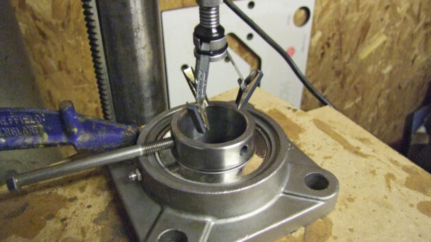
Bolts and clamps held the bearing steady during grinding on a pillar drill
I checked the diameter regularly with the vernier gauge, and after around 30 minutes, I’d ground the bearing out to the required size of 44.9mm, giving a slight clearance to make the bearing a nice sliding fit onto the stock.
As I’d suspected would be the case, there wasn’t a lot left of the carborundum stones in the glaze buster!
Bearing reassembly
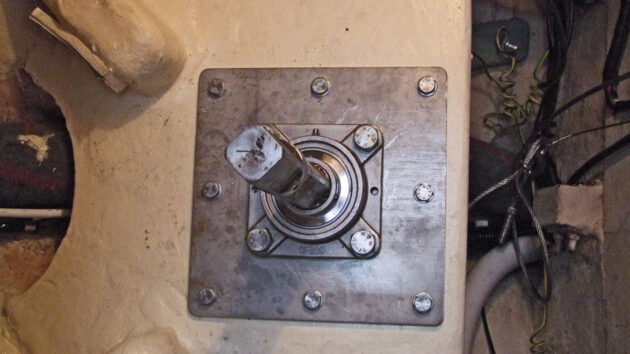
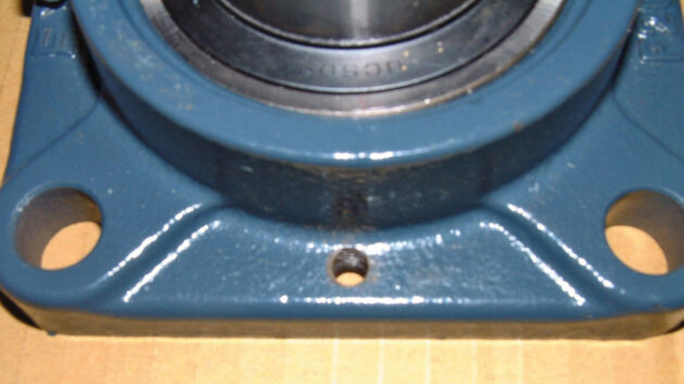
The new mounting plate and bearing in place
The new stainless steel mounting plate and bearing were next bolted into place, and the locking grub screws on the bearing tightened to hold the bearing onto the shaft.
I used a grease gun to fill the bearing with grease, a job made easier before the quadrant was refitted.
Rubber buffers
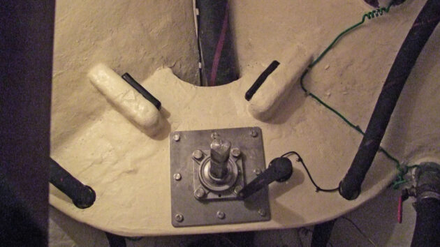
Rubber buffers were screwed to the glassfibre rudder stops
I made a pair of rubber rudder buffers from a 300mm trailer buffer, and coach-screwed them to the GRP-covered wooden stops.
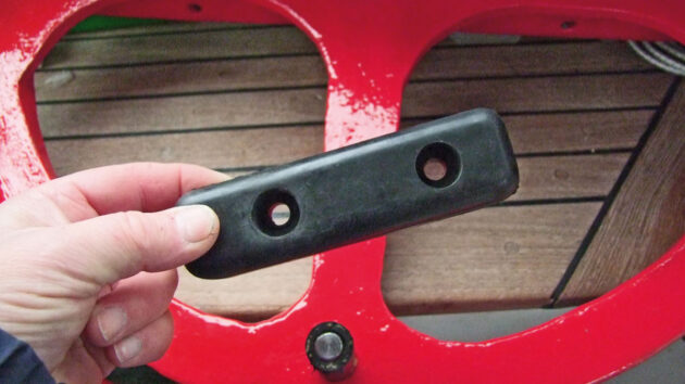
Detail of a rubber buffer and the tube-covered quadrant stop pin
I also added a piece of rubber tube to the stop pin on the underside of the quadrant.
Refitting the quadrant
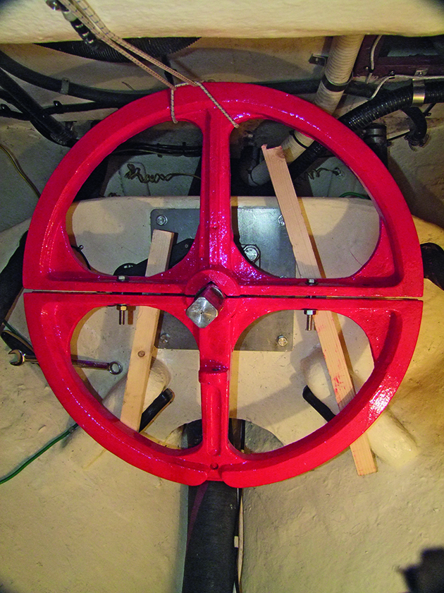
Wood blocks and shock cord held the heavy quadrant in place while the bolts were tightened
I lowered the two halves of the refurbished quadrant, which weighed around 35kg, into position and supported them on blocks and by shock cord while I bolted the two halves together.
At the same time, I adjusted the quadrant to the correct height on the rudder stock to give the required clearance between the quadrant and the rudder stops.
Shims required
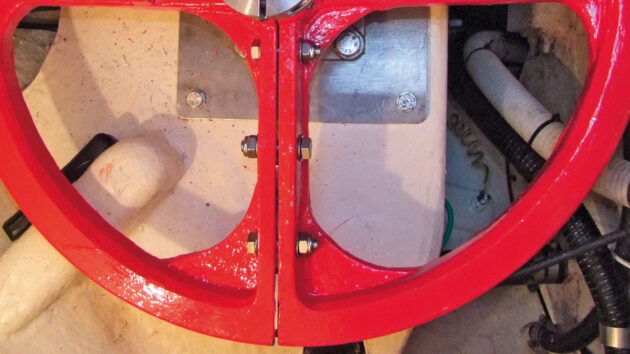
Shims were needed between the two halves of the quadrant
As I’d had the mating faces of the quadrant skimmed to give the two halves a better grip on the rudder stock, when bolted together the machining resulted in a gap of around 2mm between the two halves.
The cast iron quadrant would fracture if I overtightened the bolts at the outer edge, so I made two pairs of 2mm-thick stainless steel shims that were introduced to the gap to prevent any possibility of stressing and fracture.
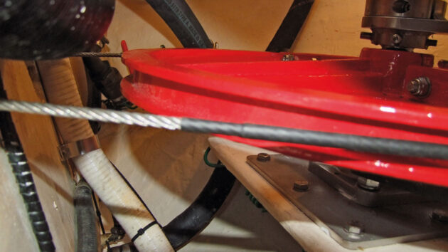
Pulleys and cables
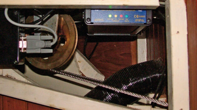
Steering cables are difficult to check properly in situ – it’s
easiest to strip them out
Next, I inspected the steering pulleys, together with their clevis pins at the base of the steering pedestal, for wear or damage. I also checked the steering cables for broken strand.
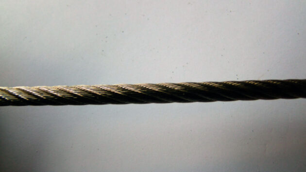
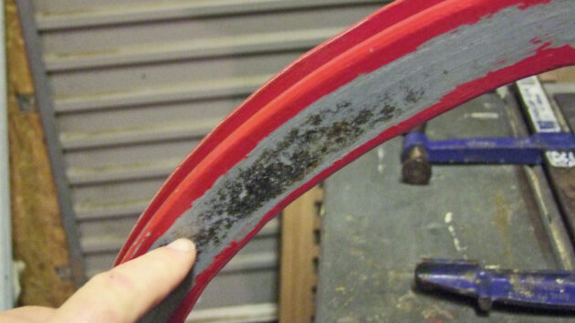
Wire cable looks fine when straight…
Broken strands can often only be found by flexing the cable into a tight bend to expose damaged wires. In this example, the straight wire looks undamaged until bent into a tight loop.
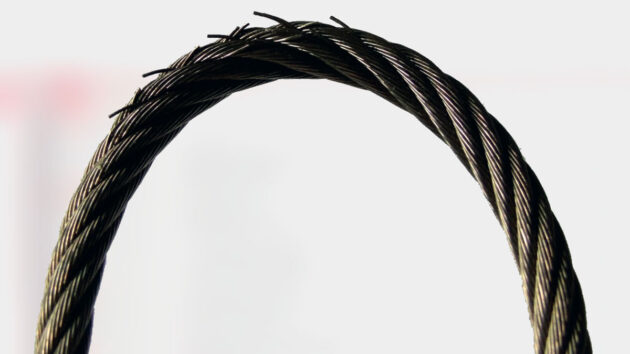
… but bending it reveals broken strands
New steering cables
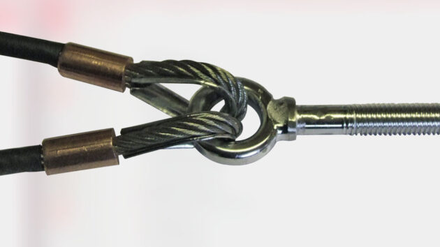
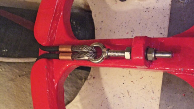
Cables were attached to the tensioning eye bolt with talurit eyes
New 6mm 7×19 stainless steel wire cables were assembled with talurit eyes at one end, spliced directly onto the tensioning eye bolt.
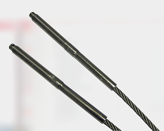
Swaged studs were fixed to the other ends of the cables
The other ends of the cables were terminated with threaded swage studs.
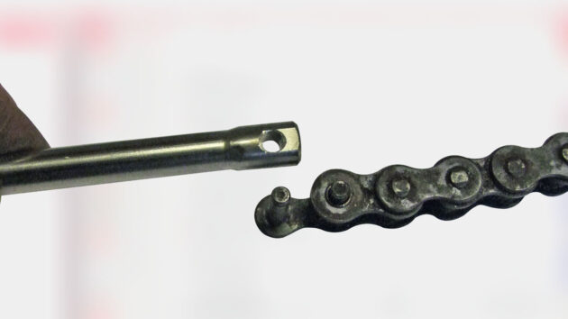
The threaded end of the swage stud was cut off, and the stub drilled to accept the chain connecting link
The threaded end of the swage studs had to be modified by cutting off the threaded section and drilling a 5.5mm hole in the remaining stub just beyond the swaged area to accept the pin of the chain connecting link.
Heat-shrink protection
Glue-lined heat-shrink tube on the cable will protect the new epoxy paint on the steering quadrant
Before assembly, I applied two pieces of glue-lined heat-shrink tube to the wire where it would bear on the quadrant to prevent the wire from chafing the protective epoxy/paint.
One piece of heat shrink tube was made 75mm longer than the other to give a tapered transition where it ran over the steering pulleys.
Centred steering
I marked the centre of the chain with a piece of twine before refitting the chain drive and steering wires onto the quadrant and drive sprocket.
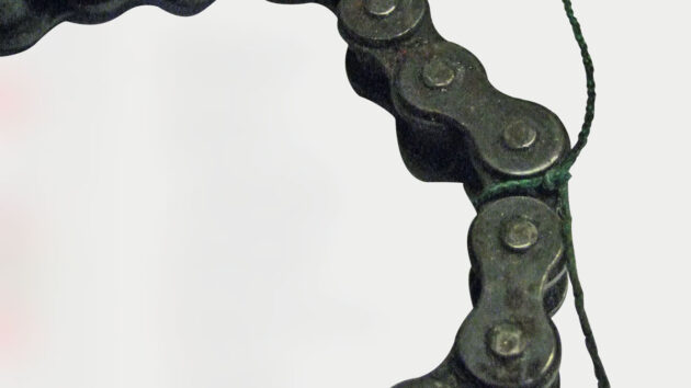
Twine attached to the centre of the chain made it easier to centralise the steering
With the rudder centralised and the ‘king spoke’ on the wheel vertical, the centre of the chain could then be dropped over the corresponding tooth on the chain sprocket.
Cable tension
Finally, I tensioned the chain with the eye bolt on the quadrant and refitted the autopilot to its separate steering tiller. It’s important not to overtighten cables, as this can cause the boat steering system to become tight.
The final job was to tighten the cables with the quadrant adjuster
After a period of settling in, it is worth checking to see if the cables have stretched, and readjust as necessary. All this work did the trick – the boat steering system is now finger-light!
How to service your outboard steering
After a midnight steering failure, one boat owner learns a hard lesson about the "fiddly" but essential maintenance of remote…

Windvane self-steering: a complete guide for sailors
Ali Wood explains how you can harness the power of the wind and sea to steer efficiently
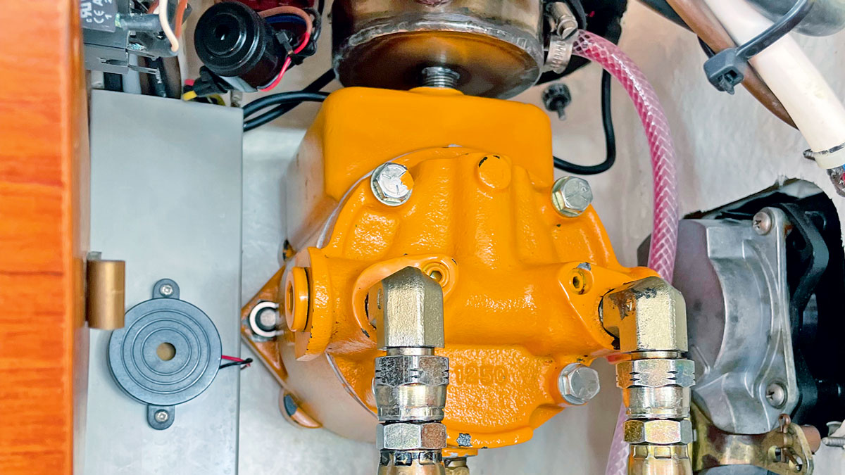
Servicing a hydraulic steering helm on a boat
After finding a hydraulic oil leak in the steering of his Nauticat 331, Mike Corp services the yacht’s helm pump…

How to replace hydraulic steering hoses and refill the system with fluid
I bought my three-year old Jeanneau Merry Fisher 855 in November. After a full survey I sailed her back to…
Want to read more articles on boat steering systems?

A subscription to Practical Boat Owner magazine costs around 40% less than the cover price.
Print and digital editions are available through Magazines Direct – where you can also find the latest deals.
PBO is packed with information to help you get the most from boat ownership – whether sail or power.
-
-
-
- Take your DIY skills to the next level with trusted advice on boat maintenance and repairs
- Impartial, in-depth gear reviews
- Practical cruising tips for making the most of your time afloat
-
-
Follow us on Facebook, Instagram, TikTok and Twitter