
Neil Fuller only narrowly avoided disaster designing and installing a bespoke holding tank for his 1980 Westerly Konsort

My Westerly Konsort Koto was built in 1980 and featured a loo outlet connected direct to the sea via a 1.5in Blakes seacock. But having decided to join the Emsworth Cruising Association summer cruise to Holland, we definitely required some means of retaining black water and being able to dispose of it via pump-out, so a holding tank was needed.
I looked on the Westerly Owners’ Association (WOA) website and elsewhere for articles about fitting a tank to a Konsort and found plenty of inspiration, including one owner who ended up fitting his tank in the bow beneath the water tank. That all looked a bit complicated to me, so in the end I decided to design my own.
The cupboard above and behind the loo seemed the ideal location for the tank, but it would only accommodate a 30lt tank, which seemed a bit small for my liking. However, by moving the cupboard frontage so it ran parallel to the cabin side, rather than at right angles to the bulkheads, I could fit a 70lt tank, which sounded a much more practical size.
I spent a long time measuring everything and when I double checked it all looked good. It was only when I made a mock-up of the tank in cardboard that I discovered it was actually too big to get through the heads door – something I hadn’t thought to measure!
Having recovered from the ribbing doled out by friends in the marina, it was back to the drawing board. I had to reduce the size down to a 50lt tank which is about as small as I would want to go. This time the cardboard mock-up did go through all the necessary apertures (just). I am just glad I found my mistake when I did.
Once happy, I drafted up the tank in detail using the Microsoft Visio programme I had on my computer.
I then committed myself and ordered a custom tank plus all fittings needed from Tek-Tanks. I looked into some cheaper options, but I went with the company that is well known and the product quality and service were excellent. I supplied my scale diagram to Tek-Tanks who converted it to a proper CAD diagram with all the elevations and a perspective view that you then have to approve. That way it’s your fault if it is not correct!


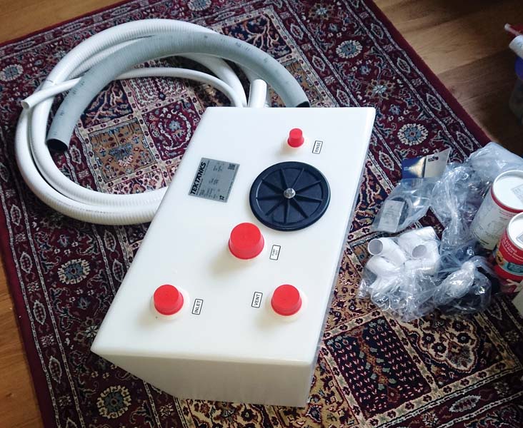
I took out the old, impractical sliding sink from behind the loo which made way for an outlet valve, in this case a TruDesign plastic ball valve (38mm). The top of the tank had connections for the loo (38mm), breather vent (38mm), pump out (50mm with dip pipe), tank flush (19mm), and inspection hatch (150mm). I specified a tank flush fitting positioned directly above the tank outlet so if things did get blocked I could easily rod through from the top all the way to the skin fitting.
The tank itself would sit on the cupboard shelf which was 10mm glassed-in ply so very strong. I had to cut a new hole for the outlet hose from the loo as this would follow a different route into the tank to that of the original syphon loop. I also had to cut a tank outlet hole. Not having any hole-saws with me at the time I drilled myriad small holes round the circumference and then joined them together using a narrow bladed pad saw, finally tidying up the edges with a Dremel.
Problem pipework
All was going very well until I started to remove the old hoses and fit the new. These hoses are the work of the devil and more uncooperative than an angry boa constrictor! The old hoses did not want to come off so in the end I cut them off at the fittings and then split them longitudinally with a multi-cutter. Bending the new ones was a trial of strength and patience. I heated them up in front of a fan heater while bending them over my knee to get near the shapes I needed. Great for muscle building! You then have to work quickly as once they cool down they become inflexible again. To get the ends over the fittings I used a combination of boiling water and a heat gun. I still had the scars on my hands from this exercise two weeks later (doing the work in January/February didn’t help the situation).
Once the inlet and outlet pipes were in place I put in wooden battens to hold the tank firmly in place. It would have been easier if I’d specified lugs on the tank base but hindsight is a wonderful thing.
The weather in February was proving to be a bit cold, wet, and wild, so I had to wait to do the deck fittings. Since bodging the holes earlier I decided to buy three hole-saws of the right size in order to make a neat job of cutting out the deck and cabin-side holes. The cabin-side hole for the tank-vent outlet was 73mm diameter; the deck holes for the flush-out and pump-out were 42mm and 64mm respectively. I had to borrow a drill with a 1⁄2in chuck from a friend as the arbour for these saws was too big for mine.
I did the vent outlet hole first as this was the easiest one to position accurately, and I only had to drill through 6mm of fibreglass. I positioned the vent inside and drew round the outline. If you remember back to school geometry classes there are two ways to find the centre of a circle. The first involves drawing arcs from various points around the circle circumference, joining where they cross each other by straight lines which then cross at the circle centre. The second is to draw a triangle in the circle with all points touching the circumference. If you then take a perpendicular from the middle of each side these cross at the circle centre. I used the second approach.
Once I had the circle centre located I drilled a small pilot hole from inside with my Dremel drill. I then double checked the deck clearance from outside before drilling with the hole-saw from the outside in. I’d not used a hole-saw for many years so made a bad start by first snapping the arbour drill. I was drilling too fast with too much pressure, so once the drill broke through the hole-saw then hit the cabin side at a slight angle, putting enough load on the drill to break it. I was lucky I didn’t make a mess of the cabin side. Lesson learnt. I replaced the drill and using a slow drill speed and light pressure successfully cut the 73mm hole.
After tidying up the hole, I dry fitted the vent, and then drilled out the holes for the self-tapping screws to fix the vent in place. I also used a countersink on these holes so the gel coat would not crack around them. Once I was ready I then applied sealant and screwed the vent in place.
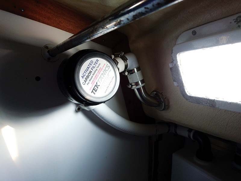
Tank vent filter in place well above any fluid level
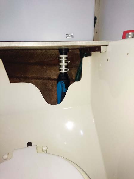
The outlet valve hose tail needed shortening to fit in the restricted space
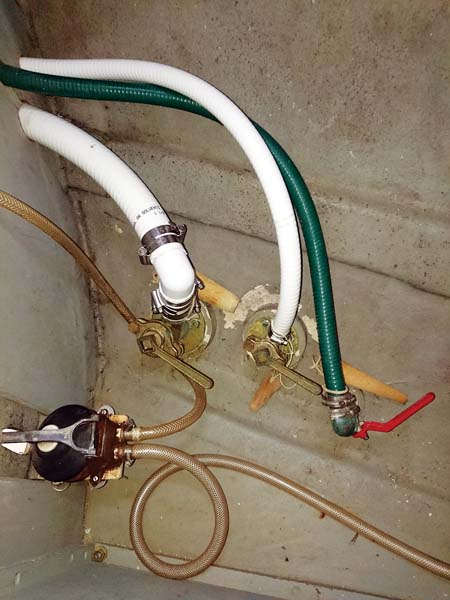
New hoses connected to the original inlet and outlet seacocks
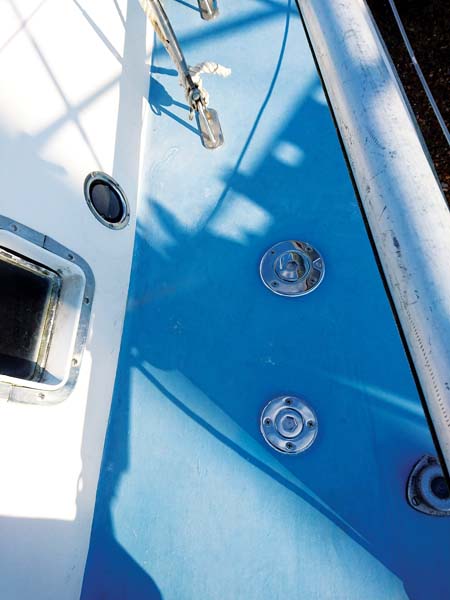
The tank vent on the cabin side, the pump-out and rinse fittings on deck
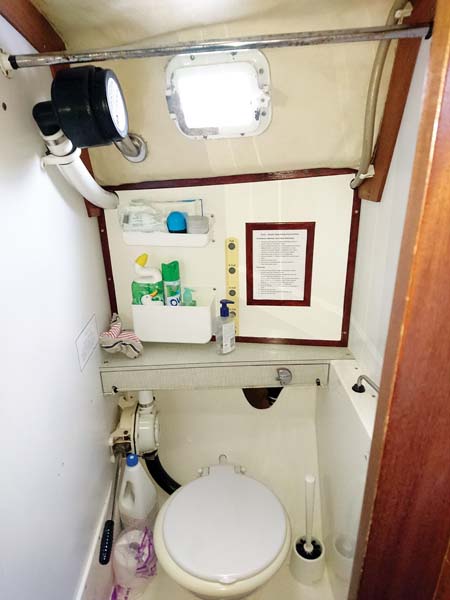
Trim fitted around tank cover and everything back in place. Note tank level indicator holes which illuminate when a push-button light shines through from behind
Deck holes
Working out the location of where to cut the flush and pump-out holes was a bit more involved. The deck has a slope, so the holes could not simply be put directly above the tank fittings. I made paper tubes of the correct length and diameter to put on the tank fittings and touch the underside of the deck. I then manoeuvred these so I had them in a position where the angle between fitting and tube and deck and tube looked the same. I then drew round these tubes and found the centre of these drawn circles. I again used my Dremel, but with its 90° adaptor fitted (not much room between tank and deck), to drill the pilot holes from inside.
Then I could drill the 64mm and 42mm holes through the deck from the outside. This was a bit more difficult to get through as the deck is balsa cored and 19mm thick in total. I once again tidied up the holes, dry fitted the fittings, and drilled the screw fixing holes as before. I next removed about 5-10mm of balsa core from around the edge of each hole and filled with glass/epoxy to prevent any water from getting to the balsa core.
As these deck fittings had to connect to hoses that then connected direct to the tank, I had to connect these hoses at the same time as I fitted the deck fittings so that everything went into place.
Note that I had to reduce the pump-out fitting length to fit. It was designed for both 11⁄2in and 2in fittings and as I was only using the 2in size I could cut off the reduced bore part to allow extra wiggle room to get the hose on between pipe and hull. This took a bit of fettling as I had to keep warming the hose with a hot air gun.
With the deck fittings screwed down and all hose clips tightened I had completed the outside works for the holding tank.
The next job was to finish the connection of the vent filter to the tank and vent. The filter needs to be above the vent outlet so water cannot get to the carbon element in the filter. I had worked out a way to do this that kept the filter out of the way in the heads but also made it easy to change the filter. Connecting all this up proved to be fairly easy and I finished off using a 50mm hose bracket to keep everything in place.
Double check everything!
To avoid time-consuming bodges, don’t skimp on templating, measuring and scale drawing and remember the limits imposed by the relative inflexibility of sanitary hose. I failed to take into account the hull’s curvature below the tank and the depth of the TruDesign valve and its fittings. The bottom outlet really needed to be another 25mm away from the hull side to allow for the outlet hose to connect the bottom of the valve with the seacock. Luckily I was able to remove 20mm from each of the three hose tails making up the tank and valve fittings, reducing the overall length by 60mm, which was just enough. If that had failed, I’d have had to fit a shorter bronze valve, or just routed the outlet hose direct to the seacock.
Finishing touches
The final task was to make a new panel to cover the tank. I used 6mm ply roughly shaped to the pattern of the old one but some 10mm longer. The bulkheads and shelf are not all exactly square, and as for the under deck line, that was something else. It took a lot of trial fitting until I was relatively happy. I then tidied finished it off with some edging and trim.
I also made a rudimentary tank level indicator by fitting a car running light strip (£4 from ebay) behind the tank, controlled by a push-button switch, so the tank can be illuminated from behind. I cut holes in the wooden panel in a vertical line, through which the light will shine above the level of the tank contents.
Components list
1 x custom-designed Tek-Tank
1 x Microvent breather filter (or equivalent)
1 x breather vent
1 x deck pump-out fitting
1 x deck tank-flush fitting
1 x stop valve
4m x 1.5in sanitary hose
1m x 19mm sanitary hose (flush out)
1m x 2in sanitary hose (pump out)
7 x 1.5in 90° elbows for sanitary hose
24 x 1.5in hose clips
2 x 19mm hose clips (flush fitting)
2 x 2in hose clips (pump out fitting)