
Mike Reynolds shares the lessons he learned about undertaking a boat engine mount replacement

How one boat owner tackled a boat engine mount replacement
While in Malaysia back in 2013 we replaced the old Yanmar engine on our 1980’s IOR ¾ ton cruiser-racer Zen Again, fitting in its place a new Craftsman (Mitsubishi) CM3.27 engine.
The new engine needed low-profile mounts to align with the propeller shaft.
Two of the four low-profile mounts ended up at the bottom of their travel. Eventually, that came back to bite us.
Fast forward to December 2022.
Zen Again was cruising the San Blas islands of Panama. We’d sailed about 30,000 miles and the engine had 1,700 hours on the clock.
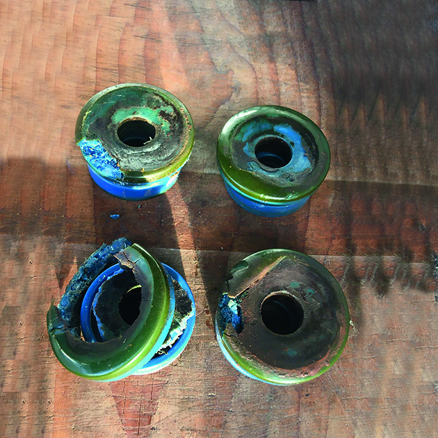
During a routine engine check, we found three of four of the mount’s polymer inserts were disintegrating.
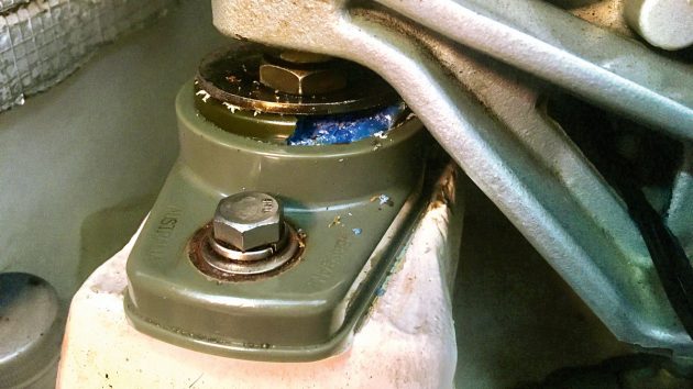
One of the old, deteriorating engine mounts. Credit: Mike Reynolds
The polymer inserts provide the shock absorbing ‘elastic’ in the mounts.
Thankfully the weather improved and we were able to cruise the San Blas with little engine use and no further deterioration.
Along the way, we contacted the Australian mount manufacturer PolyFlex.
After viewing the photos, they recommended renewing only the inserts, greatly reducing the cost.
We thought we were in for a reasonably simple job: lift the engine; remove mounts; fit new inserts; fit mounts; lower engine; and align engine to shaft.
This is the story of how a small problem can morph a project from short and simple to long and difficult. Yes, a typical boat project!
Preparing for a boat engine mount replacement
Our project started on arrival in Linton Bay Marina, about 30 miles east of the Panama Canal.
By then the new inserts were on their way to us, as were a set of small blocks to use in lifting the engine.
We had various spare blocks aboard but not enough.
We had to bus into Colon – three hours each way – several times to collect courier packages.
Thankfully, we had all the tools aboard necessary for the job.
We decided to carry out the project with the boat in a marina berth.
Hauling out hadn’t been necessary when we installed the new engine so nor would it be for this work.
While awaiting the gear we could prepare the engine for lifting.
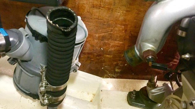
This involved detaching: power; fuel inlet and return; raw water from seacock, vented loop; exhaust; Morse throttle and gear shift controls; electrical harness to control panel and the propeller shaft coupling.
We drained the engine of oil and coolant to reduce weight and avoid spills.
We loosened the main nuts on the top of each mount. And we loosened the two bolts securing each mount to the engine bed.
The latter was a tricky job since the access holes on the inboard faces of the beds lined up with the old Yanmar mounts but not the current mounts.
Lifting the engine
With all necessary gear on hand, we could proceed.
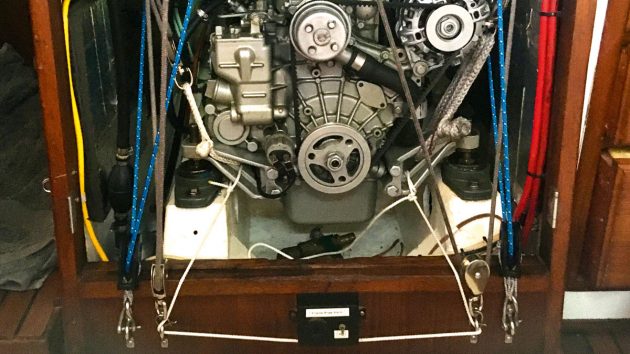
We already had four deadeyes through-bolted forward and aft at the top of each side of the engine bay, installed when first fitting the engine.
To them, we attached blocks, then reeved four lifting tackles forward and aft, port and starboard.
The other end of each lifting tackle was attached to a soft shackle around an engine mount arm.
The tails of the four lifting tackles passed through blocks at the lower forward wall of the engine bay, then two port and two starboard tackle tails were combined into one per side and fed up through the companionway.
Each led to a block hung from our rear dodger arch (which supports our mainsheets so is very strong), aft to a check-stay block on the quarter, and forward to a sheet winch.
In short, there was a lot of knitting!
The result was a winch lifting the port and another the starboard side of the engine. Two further tackles were rigged.
One hauled the propeller shaft aft by a couple of millimetres to avoid the shaft being dragged up with the engine. Another allowed us to haul the engine forward.
With all the tackles rigged and holding the engine steady, we could remove the bolts securing the mounts to the beds.
With cruiser friends manning the winches we lifted the engine sufficiently to drop the mounts off the engine mounting arms.
Wooden chocks were inserted and the engine lowered back onto them.
Refurbish and refit
With the mounts out, we could set to work refurbishing them. The mounts disassembled easily, revealing their internal structure.
Each engine mount arm fits onto the mount’s central shaft. Each central shaft sits inside a two-part polymer insert.
The outside of the inserts attaches to their base via a ‘collar’ in the central hole of the base. And the bases bolt to the engine beds.
Refurbishing was simply a matter of inspection and cleaning of the parts, except for the inserts which of course were replaced.
Reassembly was simple, with the inserts compressed by tightening a nut on the central shaft.
Correct compression was obvious since the nut bottoms-out on the unthreaded part of the central shaft.
The height of the engine is adjusted by a second nut on the central shaft, with a third locking the engine down.
Continues below…

How to service a marine diesel engine in 12 simple steps
It was time to service the marine diesel engine on our Maxi 84 cruiser. Knowing how to diagnose and fix…

5 top causes of boat engine failure – and how to avoid them
Jake Kavanagh talks to Sea Start marine engineer Nick Eales about how to avoid the five major causes of an…

How do I tell if an old boat engine is beyond repair?
Is it worth buying a boat with a non-running engine? Vyv Cox has some tips on what to look for…

Marine engine videos with Stu Davies – top tips on servicing your boat engine
When we acquired our 43-year-old cruiser Maximus, we asked PBO’s engine expert Stu Davies and wife Laura to show us…
We lifted the engine off the chocks and lowered it onto the mounts.
We then had the job of inserting the bolts and securing the mounts to the beds. We eventually came up with a cunning plan.
We fed whipping twine down through each mount bolt hole and the bed, fished it out of the inboard access hole, tied it to the bolt end and gently teased the bolt up through the hole.
This avoided losing bolts into the void under the beds.
Once through, the nut went on easily. We tightened each nut using vice grips over a hose offcut over the end of the bolt, to stop the bolt rotating.
There was insufficient bolt length to use the usual dual nut approach.
With the mounts fitted, we could offer-up the gearbox flange to the propeller shaft flange. That’s when it all went wrong.
With the engine lowered as far as possible on the mounts, it was 4mm too high. We couldn’t align the engine.
Engine out again
Engine alignment is pretty simple. Get the engine/gearbox flange in line with and parallel to the propeller shaft coupling flange.
It’s obvious when they’re badly out of line.
To get the bolts through between the flanges, we had to lift the shaft so far that the shaft seal gave up and we started to take water.
We needed to lower the engine by about 5mm to be sure of aligning and wanted 10mm to allow for future variation.
We spent several weeks discussing the problem with other cruisers as they came and went in Linton Bay Marina.
The bed tops were too thin to trim down.
The consensus was to cut off the engine bed tops and rebuild.
While simple in concept, this would have been a substantial and very messy job.
So I procrastinated and kept looking for a better solution.
In the meantime, using various tackles we slid the engine forward and up out of its bay.
We cleaned and repainted the engine bay, and thoroughly degreased the engine itself.
Elegant solution
Eventually, we discovered our saviour. Vince, an American with a local metal fabrication business, came up with a novel solution within minutes of arriving.
He suggested making new mount bases with the collar in the central hole, 10mm lower.
We’d need to cut circular holes under each mount to allow the central shaft to move. The bases would be milled from marine aluminium.
An elegant solution at last.
It took several weeks for the new mount bases to be fabricated at a metalwork shop in Panama City.
The mount bases were nicely made and assembly was very simple. Vince visited to cut the holes in the bed tops.
We smoothed and opened-out the holes to allow adjustment in each mount’s placement.
We loosely bolted-in the mounts, again using whipping twine to assist. Then we lifted the engine back and onto the new mounts.
Alignment took only an hour or two. We ended up with our desired 5mm spare adjustment range on the mounts.
With the engine aligned on its new mounts, we put everything back together.
We restored connections to power, fuel, water, exhaust, Morse controls and electrical harness.
In doing so, we replaced most of the hoses we’d removed. We also replaced oil and fuel filters and refilled oil and coolant.
And we removed all the lifting gear.
A test run showed the engine was alive.
We had several sessions diving to clean the propeller, which had accumulated a lot of growth.
We arranged for a local mechanic to check the engine, and we ran the engine in gear which showed barely discernible shaft movement.
Running the engine through its rpm range showed vibration had decreased significantly.
We ran the engine ahead and astern for an hour to finish our static testing. Subsequent sea trials also went well.
So our project was finally at an end. We’re very pleased with the overall result.
We should get five years and/or 1500 hours out of the new inserts.
The costs were £80 for inserts, £800 for custom mount bases and £800 for two months in the marina.
Had we not had the alignment problem, the cost would have been £80 for the inserts and £120 for a week in the marina!
Boat engine mount replacement: step by step
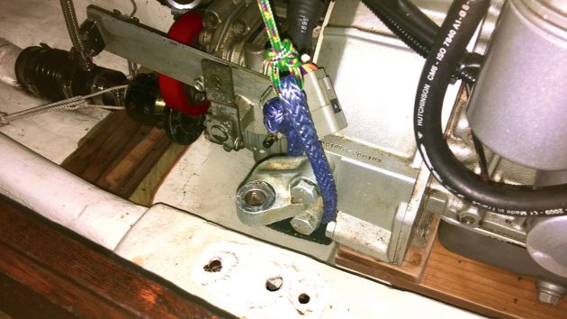
Lifting the engine to remove the mounts
Credit: Mike Reynolds
1. To remove the engine the fuel lines, raw water inlet, exhaust, throttle and gear controls, electrical harness and the propeller shaft coupling had to be disconnected.
Credit: Mike Reynolds
2. Lines were rigged to safely lift the engine out of its bay; the same technique was used to lower it back in place once the mounts had been fitted.
Credit: Mike Reynolds
3. The polymer inserts in three of the low profile mounts had disintegrated, explaining the increase in engine vibration.
Credit: Mike Reynolds
4. The engine was temporarily lowered back on to wooden chocks while the new mount bases were prepared.
Replacing the mounts and the engine
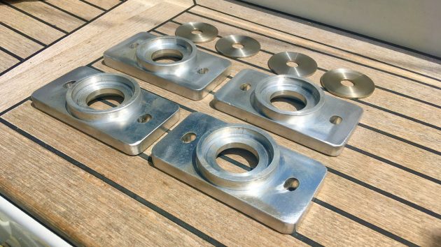
Credit: Mike Reynolds
5. Four new mount bases were milled from marine aluminium and collars were 10mm lower to allow for alignment.
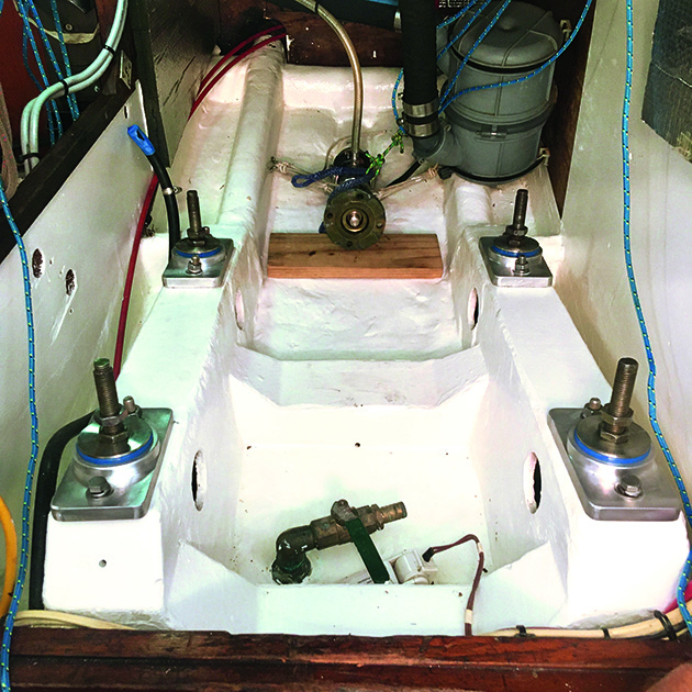
Credit: Mike Reynolds
6. The new mounts installed in the newly-painted engine bay ready for the engine to be aligned.
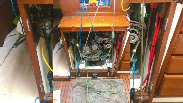
Credit: Mike Reynolds
7. By a complicated arrangement of tackles the engine is lowered back into the bay onto its new mounts.
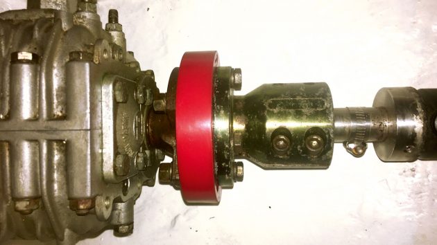
Credit: Mike Reynolds
8. The engine and gearbox can finally be perfectly aligned with the prop shaft for vibration-free motoring.
Enjoyed reading Boat engine mount replacement: step by step guide? 
A subscription to Practical Boat Owner magazine costs around 40% less than the cover price.
Print and digital editions are available through Magazines Direct – where you can also find the latest deals.
PBO is packed with information to help you get the most from boat ownership – whether sail or power.
-
-
-
- Take your DIY skills to the next level with trusted advice on boat maintenance and repairs
- Impartial in-depth gear reviews
- Practical cruising tips for making the most of your time afloat
-
-