
It could be put off no longer: the time had come to work on the bottom of our Secret 20, which meant rotating her through 180°. David Pugh reports
When we bought our project boat kit, we carefully measured to ensure that she would fit our double-garage workshop, albeit diagonally.
See the full set of articles: Building the Secret 20 kit boat with PBO.
At the time, turning her over to complete the bottom seemed so far ahead that it wasn’t worth worrying about.
But it’s surprising how time flies, and as the project progressed we gave more and more thought to the not-insignificant task of turning the boat over.
We knew from the shipping manifest that the keel weighed around 250kg, and just a couple of weeks ago we lifted the entire boat off the floor using a chain hoist with a dynamometer in line (once used by British Telecom for measuring cable tension).
This suggested that we had added about another 100kg of timber to the overall mass, and although the kit manufacturer suggested that a few strong people and some car tyres could turn the boat, we decided that manhandling 350kg was too big a risk to the PBO staff and the boat.
Aussie blokes and girls must be tougher than us Poms.

Initial sketches for our frame design, fuelled by tea
Possible methods
The first decision we had to make was whether to turn the boat inside our workshop, or in the car park outside.
The latter option was attractive in that there was virtually unlimited space to work around the boat.
However, unlimited headroom has its drawbacks, namely that there would be nowhere to mount a hoist.
Without specialist equipment such as a crane or forklift we would need to lift from below – which presents its own problems as the boat tips over the balance point – build a gantry over the top or construct ring frames.
We considered the idea of ring frames quite seriously.
By building circular frames around the hull, probably using multiple layers of thick plywood contoured to fit the hull, we could roll the boat upside down in a controlled fashion using levers while never lifting its weight from the ground.
We eventually discounted the notion for two reasons: time and complexity of construction, and the problem of lowering the boat down from its elevated position when upside down.
Cost and time also removed building a gantry from our list, leaving us to consider whether it was possible to turn the boat within the workshop.
Here, the problem was headroom: the beam of the boat measured 2.15m, the height below the rafters 2.3m – not a lot to play with!
On the other hand, the workshop has deep (30cm) rafters spaced at approximately half-metre intervals, which we already knew were stiff enough to lift the weight of the keel as we had used them to support a hoist when unloading the delivered kit.

The top frame was built square and chocked at the gunwales

A centre bar was added
The final approach
The other limiting factor of our workshop was its width.
We couldn’t simply roll the boat or it would collide with the opposite wall, so it was essential that our method allowed it to slide sideways as it rolled.
This sideways slide was the final nail in the coffin for any ideas of turning the boat without an external framework.
Although the hull is fairly stiff now, she’s still missing much of her structure below the waterline, and the concept of dragging her sideways as she rolled seemed likely to end in damage to the hull skin and frame edges.
To avoid this, and to ensure the boat remained balanced and supported during the turn, we decided to build a scaffolding frame around the centre section of the boat.
Provided we could stop the boat from shifting within the frame, this should allow us to roll the boat without damage, and give us strong points to mount our lifting equipment.
To lift, we planned to use two chain hoists at either side of the boat, suspended from strong points in the roof.
We were encouraged in this plan by PBO reader Malcolm Norris, who had used a similar method to turn his Scruffie Scintilla.

A hoist around the keel helps to move her
Designing the frame
To begin the design, we needed to know the balance point of the hull in order to avoid it tipping the frame forwards or backwards.
We found this by lifting the boat using a chain hoist and a strop passed around the keel, moving it backwards and forwards to find the balance point – which turned out to be almost exactly on frame six.
The hoist was attached to a pre-existing strong point in the roof, made by passing a short length of scaffolding tube through holes cut in the centres of two of the joists.
With the balance point found, it seemed sensible to build the frame symmetrically around it.
We pondered whether to extend it fore and aft by one or two of the hull frames, but finally opted for one each way. As the frames are half a metre apart, this meant a frame just over a metre long.
The next choice was how tightly to wrap the frame around the hull shape.
In the end, this was made simple – our first inclination, to make the frame square, would not work as the resulting diagonal would be longer than the height of the garage.
However, by cutting off the corners the diagonal would fit below the joists.
Design done, a quick internet search showed that steel scaffolding tube and clamps were readily available; even better, they could be supplied in a range of lengths at no extra cost.
Delighted to save unpleasant time spent with a hacksaw or grinder, we were able to order exactly the amount we needed to build our frame, and a few days later set to work.
Building the frame
For anyone who grew up with Meccano, being presented with a heap of scaffolding and clamps is bound to bring back memories.
Half a day’s work built us a sturdy frame which we were confident would support the boat – and the additional 135kg added by the scaffolding!

Removing stacks of wood from the garage

Taking down the light fitting
I’m going to switch to feet and inches here, as that’s how the scaffolding was sold.
We started off with two 8ft lengths laid across frames 5 and 7.
We used timber to chock them up at the edges to ensure the weight was borne by the gunwales rather than the lightweight inner deck stringers.
We tied the two together with a 4ft tube in the centre of the boat, held by right-angled clamps, and further 4ft tubes at the edges, just outside the gunwales.
From these longitudinal tubes we hung two 3ft verticals.
As the top frame was square, we set the aft tube outside the top bar and the forward one inside it, thus keeping the gap between the tube and hull as narrow as possible.
We braced the end of these verticals with a further 4ft horizontal tube.
Under the keel we slid two 1ft lengths and braced them with 4ft lengths either side, forming a channel in which the keel could sit.
This, we hoped, would hold the keel firmly as the boat turned.
This done, further 4ft diagonal tubes joined the upper framework to the lower frame.
We carefully set the vertical frames to as parallel to the hull sides as possible.
For all the joints we used right-angled clamps – swivel clamps are available, but we designed the frame not to use them in order to keep it stiff without the need for diagonal bracing.
After a final fettle and tightening of clamps, we cut scrap timber to chock the keel frame to the keel and fill the gaps between the side frames and the hull.
These would take much of the weight of the boat when she was on her side, so we made the chocks fit the hull well.
Although they were a tight fit, we drilled them to allow us to secure them to the tubes with cable ties, just in case the movement of the boat allowed them to come loose.
Finally, we trimmed off excess length on the tubes.
This was minimal – the four vertical tubes were slightly over-long, as was the forward top transverse tube.
Trimming this last was an essential part of the frame design.
The aft tube, at 2.4m, was too long to fit below the joists. However, by placing the boat correctly it could pass between two joists.
We didn’t want to have to try and line up the forward tube to do the same, and were able to trim it so that it would just clear the roof as the boat turned.

The garage door had to go as well…

We installed a second lifting point in the roof, near the wall
Getting ready to turn
With the frame built, we turned our attention to the workshop.
We had decided to start with the boat hard against one wall, which meant we needed to clear all our stocks of plywood and many of the solid wood parts of the kit, which were either stacked against the wall, shelved on brackets or hung from the roof.
With that done, the next obstacle was one of the light fittings.
Power off, and a few screws later the joists were clear in the area required.
That left the door. A typical up-and-over double garage door, its framework was significantly lower than the roof and would foul the boat as it turned. It would have to go.
I won’t go into detail of how we removed it, but suffice to say I’m impressed at how well the spring mechanisms counterbalance those doors – it was heavier than we thought!
Once gone, we finally had enough headroom to make the turn – although the transom would project through the door aperture, the beam was narrow enough at that point not to present a problem.
Finally, we installed a second lifting point in the roof, using the same joists as the centre point, but located close to the wall.

The final frame. The diagonals at the bilge reduce its width for turning

Lifted just enough to remove the bracing

Hardboard under the frame helped it slide

Lowering her onto her port bilge

Approaching the halfway point

Very close to the ceiling
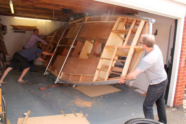
Turning her over
The first task was to remove the keel bracing. With a hoist from our centre lifting point, we lifted the boat just off the ground, then unscrewed all the bracing.
People either side balanced her as we did so, then lowered her to the ground again.
We then relocated the centre hoist to the top bar of the frame on the port side, and passed a strap from the bar at the turn of the bilge on the same side under the keel before connecting it to the hoist on the starboard side, forming a kind of parbuckle.
Lifting on both hoists now caused her to skate sideways from her position in the centre of the garage towards the wall.
We used hardboard under the frame to facilitate the slide.
Once in position, we eased the port hoist to lower her gently onto her port bilge. Again, hardboard helped protect the floor from the steel frame and made sliding easier.
We then transferred the port hoist to the starboard upper tube, ready to take the load as she rolled over.
The next bit was the bit which concerned us most, but by lifting on the starboard hoist, the boat parbuckled over relatively easily, sliding towards the wall as she went.
We found the slide quite easy to control, as she would only do so when significant weight was lifted from the floor.
The frame passed the halfway point easily, with the widest part passing between the joists as planned.
However, we realised before she went past the balance point that the centre hoist could not be shortened enough to prevent her from tipping over without control for a short distance – not a risk we wanted to take.
To help control her, we passed a rope from the starboard bilge tube around the tube in the garage roof, then back around the same point of the frame before taking several turns around another tube on the frame.
We could then ease this like a winch, controlling her as she passed the balance point.
When she had gone far enough, the centre hoist took charge, gently lowering her to the floor and onto some waiting tyres to give her a soft landing.

Just before the balance point. Note the rope to control the roll

Once over the balance point, the centre hoist takes charge

A few extra tyres from Westover Jaguar…

…have given our project boat a comfy bed to sit upon
PBO conclusion
As it happened, thanks to a bit of prior planning the whole exercise was fairly uneventful. Once she was turned, the centre hoist allowed us to manoeuvre her back into the workshop on her customary diagonal, and a few extra tyres from Westover Jaguar, our office landlords, have given her a comfy bed to sit upon. Even better, we now have a proven method of turning her without damage, which gives us more confidence that we can get her upright again without destroying our handiwork once she’s nicely sheathed and painted.
As published in the Summer 2017 issue of Practical Boat Owner magazine.