
A turbocharger on an engine is an effective way to get extra horsepower, improve fuel consumption and emissions. But when a turbo goes wrong it’s definitely time to call in the experts, as David Parker reports
The indication that something was seriously wrong was the black smoke coming from the exhaust port in the transom.
Clearly I had a problem with the portside 75hp Yanmar engine on my twin-engined 7m (23ft) Seaward motorboat – but this was a problem which came with the extra dismay caused by the sinking feeling that it was somehow self-inflicted.
The problem had begun with a smear of oil which had constantly appeared at the junction of the intake manifold and the coupling connecting it to the air duct which cooled air from the turbocharger. It first appeared shortly after I bought the boat, but only seemed a minor problem with no apparent serious effects.
I lived with it for a few seasons and had taken pictures of the weeping leak to various marine engineers in yards and at boat shows, but no one could suggest what it might be.
So eventually I decided to investigate it myself. After cleaning the air filters, I stripped down the intake manifold to inspect the gasket at the coupling. Now I saw the problem. There was no gasket: someone in the past had removed the coupling and then put it back without one.
It was only after I fitted a gasket and reassembled everything that the problem with the smoke
started – particularly when the engines were under load.
I can only hazard a guess that a period of idleness with the air intake assembly stripped down and then nursing the engines had caused a crucial build-up of soot and corrosion, which then resulted in the turbocharger itself becoming seized up.
Prior to fitting the gasket, the slight weeping of oil had also caused me to go easy with the engines for a while before I had time to sort things out. I had mainly been operating at low speeds with only occasional bursts of high power. Also, my habit of lazy river journeys and slow speeds in lumpy weather conditions had meant the engines weren’t really getting the workouts that diesel engines need for a long, healthy life.
At low power, the exhaust flow had not been sufficient to operate the turbocharger efficiently – and as the build-up of oily soot became worse, the overall problem got worse too. This under use, coupled with very gradual general corrosion over time, meant I had a turbo which would no longer turn.
It was time to call in the experts, so I took the turbocharger unit for reconditioning at specialists Universal Turbos in Fordingbridge, Hampshire.
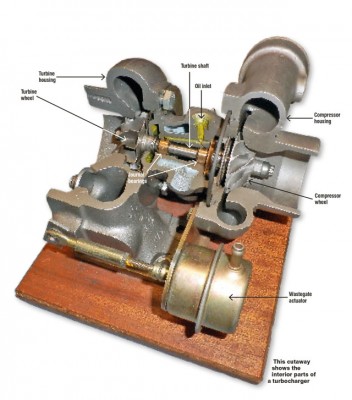
Turbo power: how a turbocharger works

Aluminium corrosion can be a particular problem in the marine environment
Turbochargers improve the performance of an engine by forcing more air into the cylinders during the combustion process. An engine without one, which draws air into the cylinders during the induction stroke at atmospheric pressure, is known as ‘normally aspirated’. The turbocharging process means more fuel can be mixed with the greater quantity of air, allowing more energy to be released which produces higher power.
More air is pumped into the engine by a turbine driven by the engine’s exhaust system. As exhaust waste gases leave the engine they are directed onto the blades of a turbine, which causes it to spin at very high speeds of 100,000rpm or more (the faster an engine runs the more the turbine spins: my boat’s turbos are rated at up to 160,000-170,000rpm).
The exhaust turbine is connected to a shaft that drives a compressor wheel which draws air in through the air filter and forces it under pressure to the inlet manifold and on into the cylinders. To cool the hot compressed air from the turbocharger it is passed through an air cooler fed by cooling water. The turbocharger is lubricated by oil from the engine’s oil pump and the internal shaft bearings float on a film of this oil.
The principles themselves are fairly straightforward and turbochargers allow smaller, lighter engines to be used: these not only give better performance but improve fuel consumption and produce better emission standards. Most diesel cars now have a turbo – partly for performance and partly to meet emission standards.
The high temperatures and speeds turbos operate under demand that units require precisely-tooled machine parts – for example, they don’t use seals but very small piston rings. Components also operate at very fine tolerances, and these tolerances can become worn. This causes an imbalance, making the turbine shaft vibrate, and foreign matter such as soot/grit particles can work their way through to bearings which become scored. A build-up of carbon, rust and corrosion is often a particular problem on boats due to a combination of underuse and operating in the marine environment. Aluminium components in particular are vulnerable to corrosion.
Tips to give your turbo a long, trouble-free life
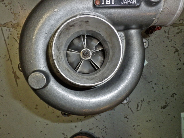
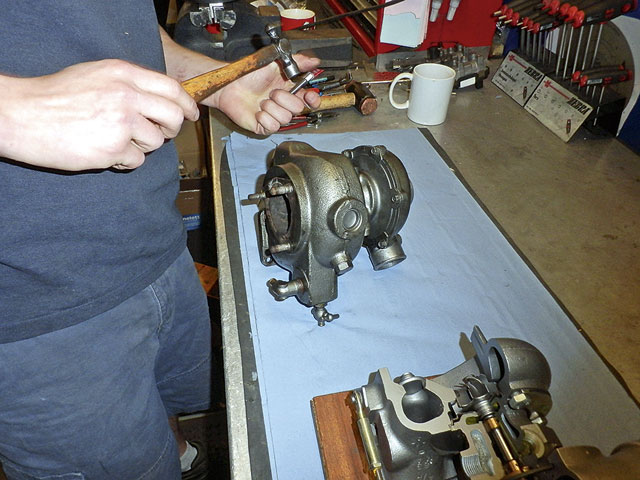
If a turbocharger will not turn freely, do not try to force it. This turbine compressor wheel has suffered major damage, possibly by someone trying to free it with a screwdriver
One thing not to skimp on is the quality of the engine oil used, and to maintain the life of a turbocharger it’s very important to regularly change that oil.
And turbos like clean fuel: dirty fuel can produce dirty exhaust which goes through the exhaust compressor wheel, causing it to clog up with soot – so change the fuel filters regularly.
It’s also worth raising the question of fuel additives. Mention fuel additives to engine manufacturers and you’ll typically get them sucking air through clenched teeth and shaking their heads: they don’t recommend them. However, speak to marine engineers and you’ll find that a lot of them do use and recommend additives, so it’s up to you whose advice you choose.
One thing they will all tell you, though, is that in day-to-day operation it’s important to never stop a turbocharged engine from full power because this will damage it. Each time the engine is used it should be left to idle for a couple of minutes to ‘spin down’ and cool while oil circulates before stopping. Switch off when hot and ‘heat soak’ can occur which means the oil left in the bearings burns, causing soot which will block up oil galleries and lead to seized bearings.
Reconditioning costs
Part of the cost with this job was a new sleeve welded into the previously corroded exhaust port in the turbine housing
The price of reconditioning a turbocharger obviously depends upon the work required: in my case the cost was £450 for this IHI RHB5 turbocharger. Various rebuild kits are available, but if parts are worn it is important to ensure only suitable replacements are used.
James Hard, technical director of Universal Turbos, warns against the cheap rebuild kits which can bought online and which could misshape or degrade quickly, causing even more damage.
It is possible to service a turbocharger yourself if no significant damage is present, but it is crucial to ensure the correct tolerances are used. If the land where a piston ring sits is damaged, for example, it will need to be machined out, and this is a specialised job – as is balancing the turbine shaft after reassembly.
Many thanks to Graham Page, James Hard and the team at Universal Turbos for their assistance with this article. www.universal-turbos.com
Here’s how to strip down and reassemble a turbocharger…
Stripping down the unit
The first job was to strip down the turbocharger to examine the individual components. The unit itself came apart in a fairly straightforward manner. From his initial inspection, James Hard at Universal Turbos could see that there were no moving parts that were actually damaged, although the corrosion on the exhaust housing was evident. However, this visual assessment could only go so far because critical tolerances could only be checked once the whole assembly was thoroughly cleaned.
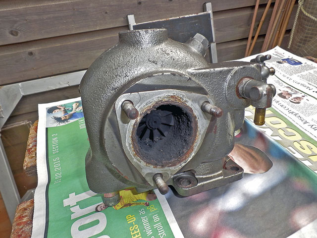
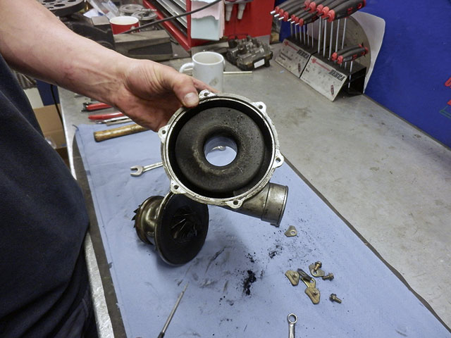
1: This is what the exhaust port looked like once the turbocharger had been removed. The build-up of soot, carbon and corrosion can clearly be seen, and this had caused the turbine wheel to seize up.
2: Before any strip-down work started, James made punch match marks on the casings to show how the turbine chamber, bearing chamber and blower chamber are bolted together.
3: James removed the mounting bolts and retaining plates of the turbine housing to gain access to the turbine wheel. Here the heat shield retaining plate can be seen behind the wheel.
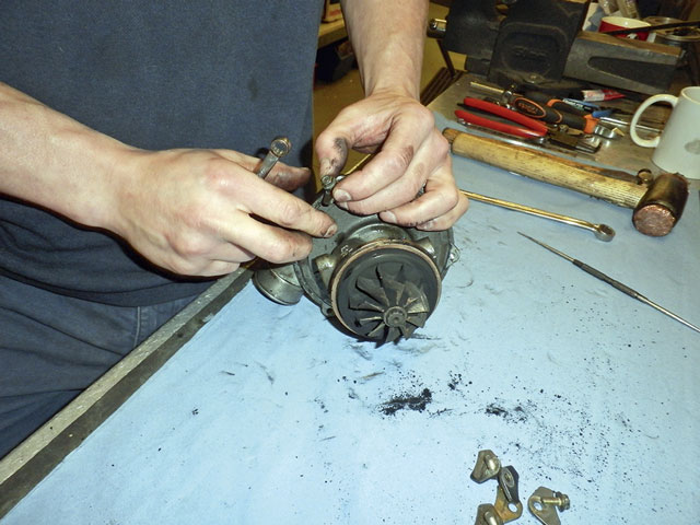
4: After clearing away the accumulated soot, James inspected the turbine wheel where it exits from the bearing chamber on the exhaust side and checked for any signs of damage on the turbine blades.
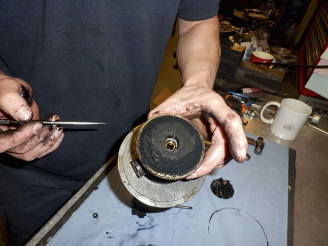
5: When the M5 mounting nuts of the compressor cover were removed, the internal build-up of grime and oily deposits were obvious.
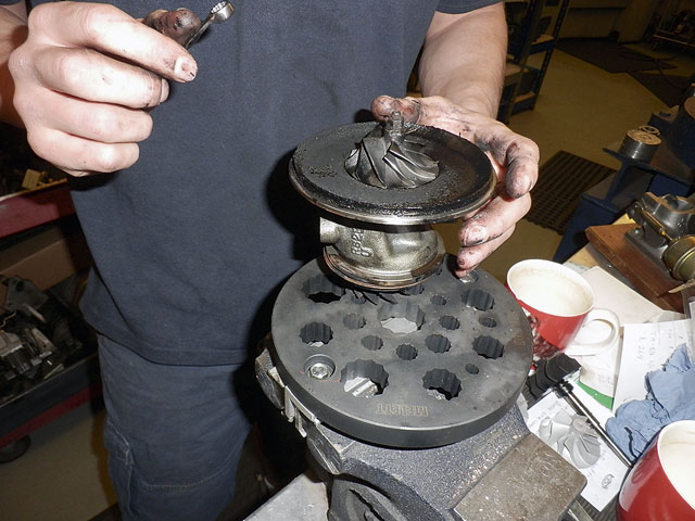
6: This is the bearing chamber itself with the compressor wheel uppermost. A turbine wheel jig was used to hold the assembly firmly in a vice while the compressor wheel was removed.
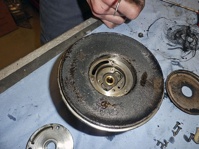
7: The turbine wheel has also now been removed, revealing a build-up of soot and carbon on the turbine side of the bearing housing. In the centre is one of the floating bearings which support the turbine shaft.
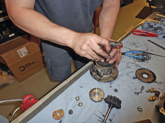
8: Care and specialist knowledge are important at every stage. For example, there is a left-hand thread on the turbo wheel: try undoing it the wrong way and you could strip it. Here the correct Torx screwdriver was selected to take out the seal plate.
9: This is the compressor side of the bearing chamber once the turbine and compressor wheels had been removed. A seal plate (bottom left) thrust collar, bearing and oil thrower were removed to show the brass floating bearing on this side which supports the turbine shaft.
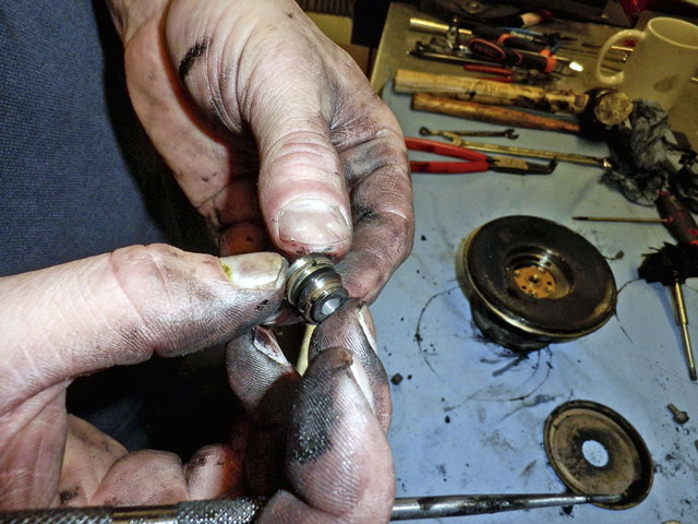
10: Finely-machined components are used in the manufacture of a turbocharger, as shown here with the thrust collar. Fixings and components can easily get damaged if they are removed incorrectly.
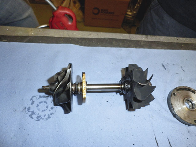
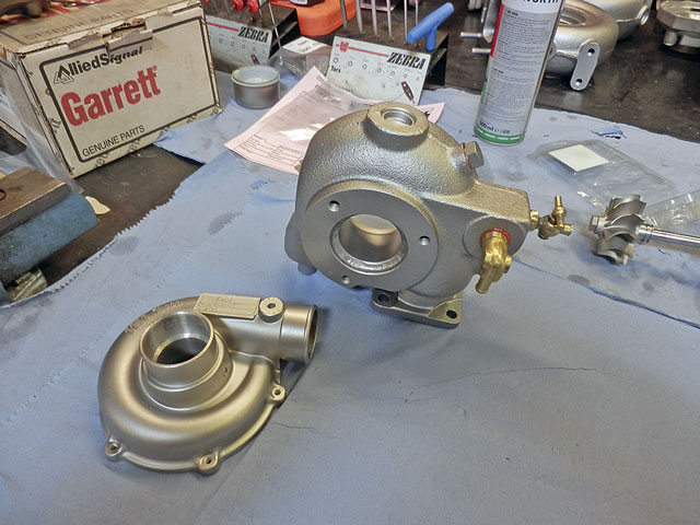
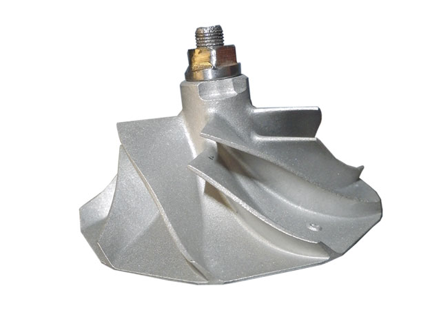
11: This, at its heart, is what constitutes a turbocharger. Two spinning turbines on a shaft, one driven by exhaust fumes to power another which draws in compressed air. The compressor wheel and brass thrust collar are on the left and the turbine wheel on the right.
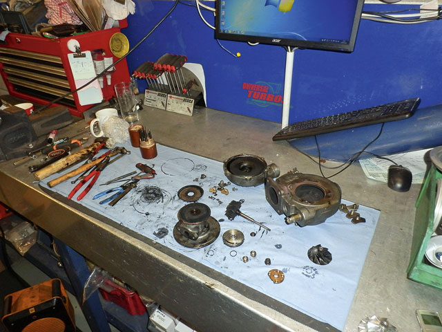
12: The components of the turbocharger, stripped down and ready for cleaning. Intricate parts of the assembly were cleaned by hand and items such as piston rings and circlips replaced. Larger parts went for degreasing, hot washing or specialist blasting.
Reassembling the turbo
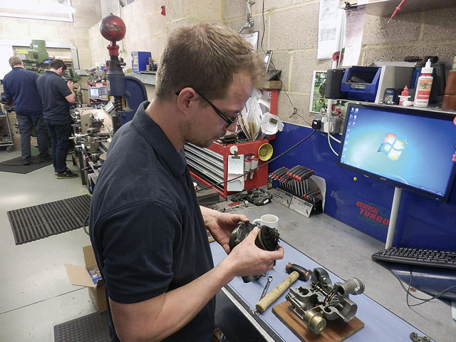
Universal Turbos has two distinct sides to its facilities: one is known as the ‘clean’ side where the engineers have their impressive range of tools and well-ordered workbenches. The other part of the workshop is where most of the serious component cleaning takes place with the specialist washing and blasting machines. Next to this is also a double-height warehouse section literally stacked to the ceiling with turbochargers for spares and rebuilds.
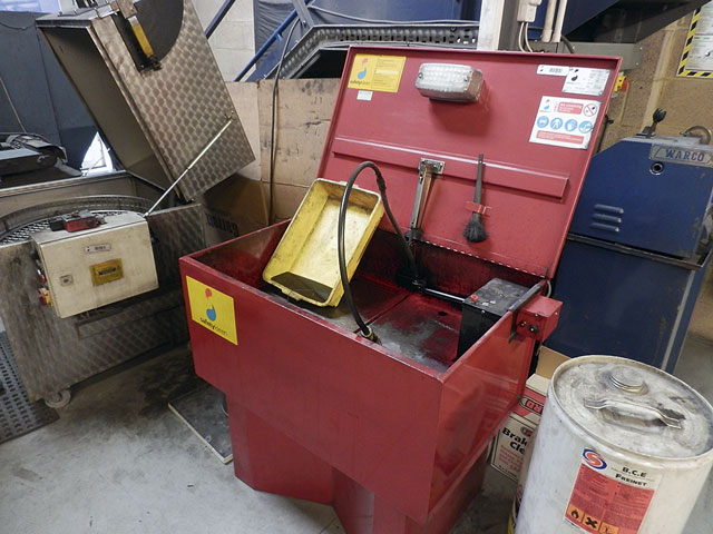
1: In the first stage of the cleaning process the components go through a degreaser which uses non-aggressive chemicals to get rid of grease and oily deposits.
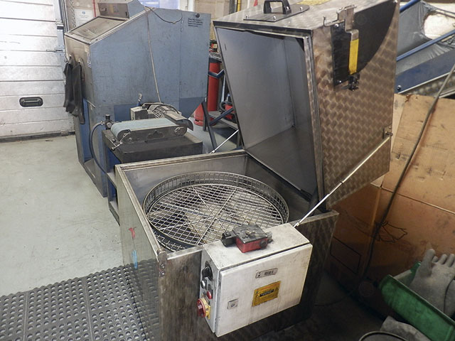
2: Next they are put through a commercial hot washer. This is basically like a giant dishwasher operating at 80°C which uses recycled water to remove scum and debris.
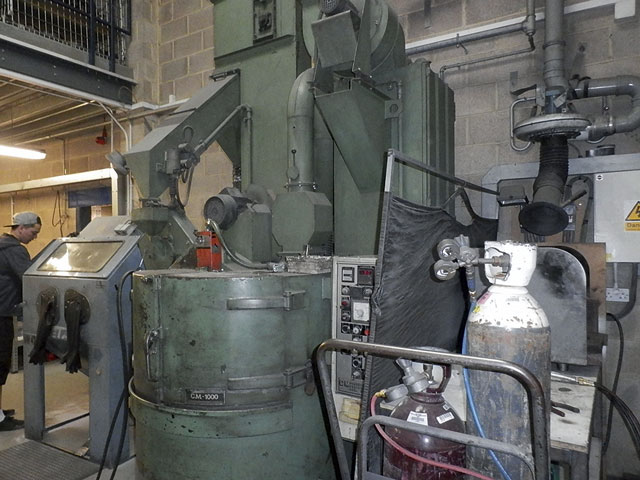
3: Tough carbon deposits are removed in this blasting machine. A hand wand allows detailed cleaning of components that need careful blasting.
4: As soon as casing parts are thoroughly cleaned they are spray-painted to avoid ‘flash rust’. Sealants are selectively used in the rebuild process, as with the water fittings on housings.
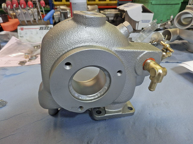
5: A smooth, shiny new stainless steel sleeve has been welded into the exhaust port of my turbine housing, which had suffered heavy pitting and corrosion over time.
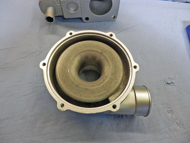
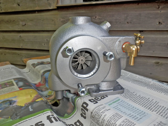
6: Here’s the compressor cover after cleaning – quite a transformation compared to how it looked when first disassembled.
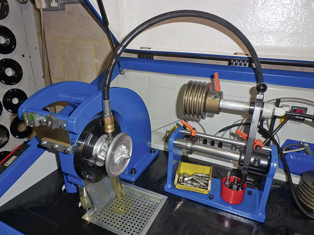
7: After reassembly of the CHRA (centre housing rotating assembly) a critical area of the rebuild is the balancing of the shaft and wheels, which is carried out using this special machine.
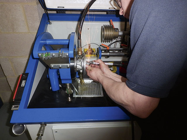
8: As the shaft is rotated at high speeds the machine records areas where it is out of balance. James can then stop the shaft and grind out small shavings of the shaft nut at the appropriate spot to counteract this.

9: The graphic display showing data from the dynamic balancing machine. The lower graph line shows that after James’ delicate grinding, the necessary parameters have been achieved.
10: Only a tiny amount of metal needed to be removed from the locking nut to achieve the correct balancing of the shaft –perfect balance is important, not least to avoid ‘turbine whine’.

11: Graham Page reassembles the unit after it has been rebalanced. New mounting screws and studs for the exhaust mixer elbow are also fitted at this stage of the rebuild.

12: The turbocharger reconditioned, reassembled and ready for refitting to the boat… the only trouble is I have twin engines, so now I’m wondering what the other one looks like on the inside!