
Jeremy Butler begins work on the first Western Skiff MkII using pre-cut plywood parts from Jordan Boats. Nic Compton reports

Finally, after months of planning and discussion, the moment of truth had arrived: the first Western Skiff MkII kit, put together by Jordan Boats, was being delivered to its first customer. Having built one of the original skiffs 22 years before, I’m not sure who was more excited: me or the boat’s newest builder, my friend and fellow ‘river rat’ Jeremy Butler.
Download your own set of free plans today: pbo.co.uk/western_skiff
Browse the complete set of articles in this series online

Nigel Irens sails the prototype skiff
The Western Skiff was originally designed by that doyen of racing multihulls, Nigel Irens, and was briefly available as a kit through Classic Boat magazine in the late 1990s. For years, Nigel and I had discussed the idea of making the boat available again, but the idea finally gained some traction when an article about restoring my skiff was published in PBO June 2018, and the arrival on the scene of someone willing to turn the CNC files into a set of PDFs for amateur construction: Jack Gifford (jackgifford.co.uk).
Nigel suggested giving the plans away for free, in the spirit of ‘open software’, and Alec Jordan of jordanboats.co.uk agreed to resurrect the kit.
And so, the first authorised Western Skiff to be built for two decades was delivered to Jeremy’s house overlooking the River Dart – just a stone’s throw from where the original skiff was conceived, built and tested.
The kit in the 1990s was supplied with everything needed to build the boat (and the cost reflected that).
Alec Jordan’s new kit is limited to the plywood parts, MDF building jig and templates for the solid timber parts, allowing builders to build their boat to a budget. The Western Skiff kit is available priced from £940 (rowing version) from jordanboats.co.uk
The free plans available to download from pbo.co.uk include templates of all the parts (ie you need to purchase your own plywood, timber and MDF, mark it up from the plans and cut the parts yourself) and comes with its own set of instructions. For amateur use only. Please make a donation to the Ed Burnett Memorial Fund at www.justgiving.com/remember/201501/Ed-Burnett

Driving down the cost
Some of Alec’s changes were driven by a desire to keep the cost of the kit down as much as possible. So, whereas task 1 with the original kit (and the free plans) was to liberate the finger joints at the end of the planks, and glue together the actual planks while they were still nested in the sheets of ply – creating a cumbersome pair of 4ft x 16ft plywood sheets – Alec Jordan has nested the planks more efficiently to reduce the amount of wastage. This has allowed him to save 1.5 sheets of ply (with a corresponding saving in the kit price) but it has also meant finding an alternative system of aligning the planks while they are glued together.
Gone are the long, elaborate finger joints of the original kit. Instead, the builder can choose between short finger joints, backed on the inside with GRP, or, in Jeremy’s case, conventional scarfs.
Indeed, setting up a jig and cutting the scarfs was one of the most time-consuming and tricky jobs of this part of the build (4 hours) – something to bear in mind when deciding which method to go for. The finger joints are less pretty but much easier for a complete beginner.
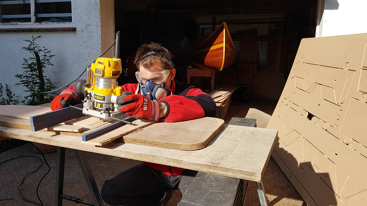
Setting up a jig to ensure his router would cut each of the faces of all the scarf joints on a consistent angle took Jeremy Butler 4 hours – one of the most time-consuming single elements of the first part of the build

The free downloadable PBO plans offer a simple set of finger joints to ensure the planks and bottom boards align correctly
In the end, Jeremy came up with a simple jig which he could run a router over and cut the exact same angle in the ends of all the planks. For those of a less technical persuasion a plane or even a belt sander can be used to make the scarfs.
With the scarfs cut, it was time to line up the two halves of the plank. Here, Alec has come up with an ingenious method to make sure they are correctly aligned. A hole is precut at the outer end of the two half-planks, with another hole cut through both parts of the scarf joint.

Alec Jordan’s ‘string method’ helps builders line up fore and aft ends of the bottom board and planks
The scarf is fitted together (without glue to start with) and a tack is placed through the hole and gently nailed to the base (worktop, floor or whatever) allowing the joint to ‘pivot’ slightly. Two more tacks are put into the holes at either end of the plank and a string stretched between them. When the string passes directly over the tack in the scarf joint, the two halves of the plank are perfectly lined up.
Then it was time to get glueing. Jeremy opted to use MAS epoxy, mixed with white colloidal silica and brown microballoons depending on the consistency he was trying to achieve. More colloidal silica makes the mix stiffer and harder to sand down, while more microballoons makes it easy to sand down but more likely to sag. MAS also supplied their own general purpose ‘Workshop mix’ thickening powder, which is what Jeremy used for glueing purposes.
“These are the most important joints you’re going to make in the whole boat, so you’ve got to get them right,” Jeremy says.
“I made sure both sides of the joint were primed with liquid epoxy, and then made a thicker mix for the glue. Make sure the glue is evenly spread, then put a bit of weight on it – but not too much because you don’t want all the glue to squeeze out.”
By lining up the two joints over the central tack – so the tack ran through both scarfs – Jeremy was able to glue up the garboards as a pair, one on top of the other, using sheets of plastic to stop them sticking to each other. He did the same for the next plank along, and planned to do the same for the rest of
the planking.
Building the jig
Next, the parts for the building jig could be popped out of the MDF sheets and assembled, using wedges to lock the lugs into the slots. It’s important to follow the order specified in the instructions – attaching the narrow side first, and the widest bit last – otherwise you’ll end up having to dismantle it all and start again, as Jeremy did! To raise the jig to a better working height, Jeremy fitted a pair of angled legs at either end (not included in the kit) – though you might just as easily sit the whole thing on a pair of trestles.

CNC-cut parts for the MDF building jig as they arrive with the Jordan Boats kit
It’s a good time to clean up the frames and round off all the corners while they’re still easily accessible.
Once ready, they all slot easily into place on the jig, along with the apron (inner stem) and transom – though unlike the original kit (and the free plans) the thwarts themselves aren’t fitted just yet.
With the frames in place, the bottom board can be fitted and screwed down. That’s swiftly followed by the garboards which are ‘hung’ on either side of the bottom board – not as I did 22 years ago, using a forest of closely-spaced cable ties, but using the least number of ties necessary to achieve a fair curve – in Jeremy’s case, just three ties per side.

Plastic cable ties keep the curve of the garboards under control. The advice is to use as few as you can get away with…
Like me, Jeremy struggled to fit the garboard to the apron and in the end had to resort to several screws to bring it in line – but perhaps that’s just the nature of garboards.
Time-served shipwrights will have noticed there has been no mention of bevels so far – not on the frames, or the ‘lands’ between the bottom board and the garboards, or even the edge of the transom. CNC cutters cut at right angles and, rather than fight this, it’s been turned into a feature: the objective isn’t to achieve close-fitting joints but to celebrate the gap. All the voids left between the various components will be filled with a nice bulky ‘fillet’ of epoxy which will not only close the gap but add a great deal of strength to the structure.
Thus the gap between the bottom board and the garboards should be taped up on the inside, primed with liquid epoxy and then filled with a large fillet of epoxy filler. The first three planks can then be sealed with epoxy and sheathed, to give a beach-proof bottom, or, as in Jeremy’s case, you can fit the next two planks and sheathe the bottom five planks. This will add a little weight but save against damaging the lower chine when dragging the boat up and down the beach.
Cost so far
Kit £992
Gloves/mask, etc £59.90
Screws £6.98
Epoxy £138.60
Glass mat £85.50
TOTAL £1,282.98
Time so far (hours)
Cutting out planks 3
Cutting scarfs 4
Glueing planks 2¾
Cleaning up planks 2½
Cutting out jig 1½
Assembling jig 1½
Jig legs 1
Cutting out frames 4
Setting up frames 3
Fitting planks 9
Filleting seams 3
Cleaning up 1
TOTAL: 36¼
In pictures: the first few steps
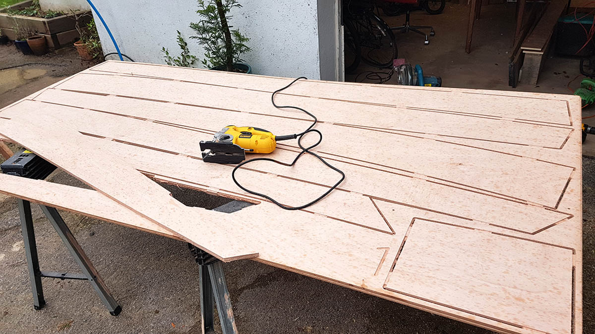
1. The plywood parts are held in place by wooden ‘tabs’ which have to be cut to release the parts. This part of the process took longer than Jeremy expected – nearly a quarter of his time so far. He found a Japanese rasp ideal for cleaning up the cut tabs afterwards.
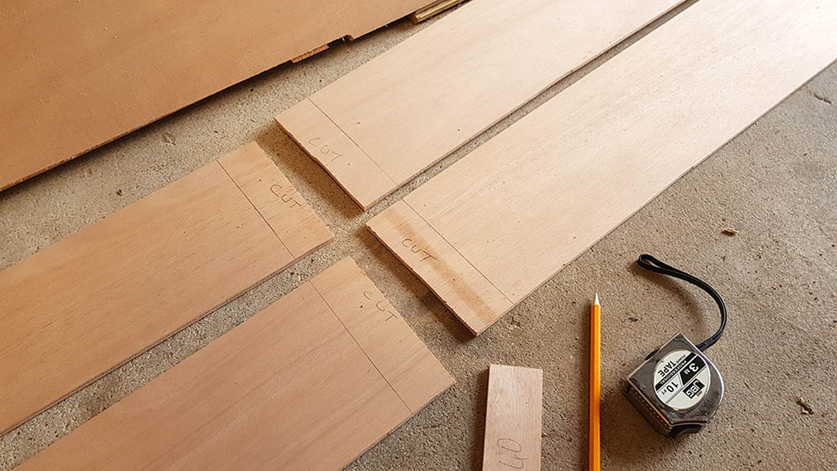
2. The Jordan Boats kit offers two options for joining the planks: short finger joints backed with GRP or traditional scarfing joints. Jeremy opted for the scarfs, which he measured up here to give a ratio of 6:40, or about 1:7.
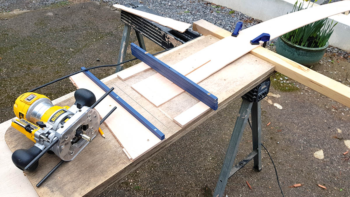
3. He built a simple jig to produce the desired scarf angle. The guides of the router will run over the blue strips of wood, with the plank held firmly in place underneath.
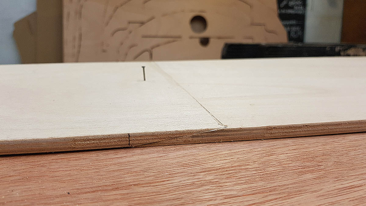
4. To ensure the planks were correctly aligned, a tack was tapped through the pre-drilled hole on either part of the scarf. The hole is deliberately not centred to make sure the plank-halves are not flipped by mistake.
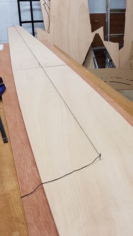
5. A string is then stretched between two pre-drilled points at each either of the plank. When the string lines up over the middle tack, the plank is aligned.
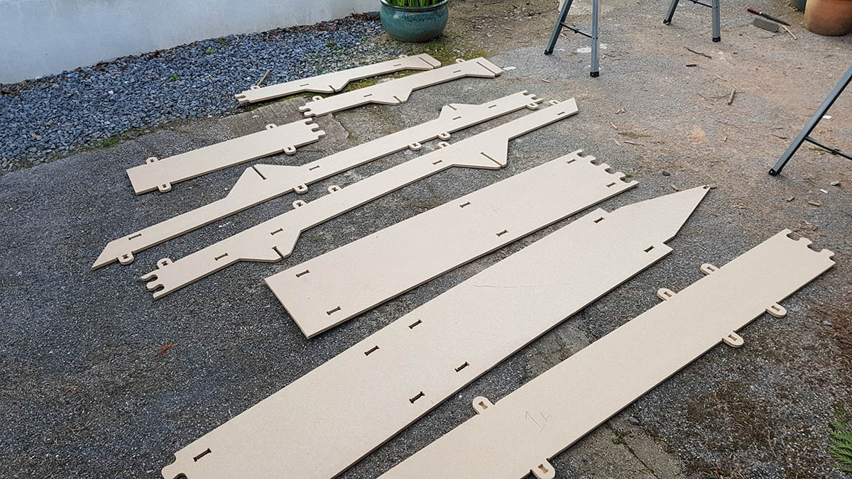
6. The components of the building jig are broken out of the MDF sheet and ready to assemble. It’s important to put them together in the correct order…
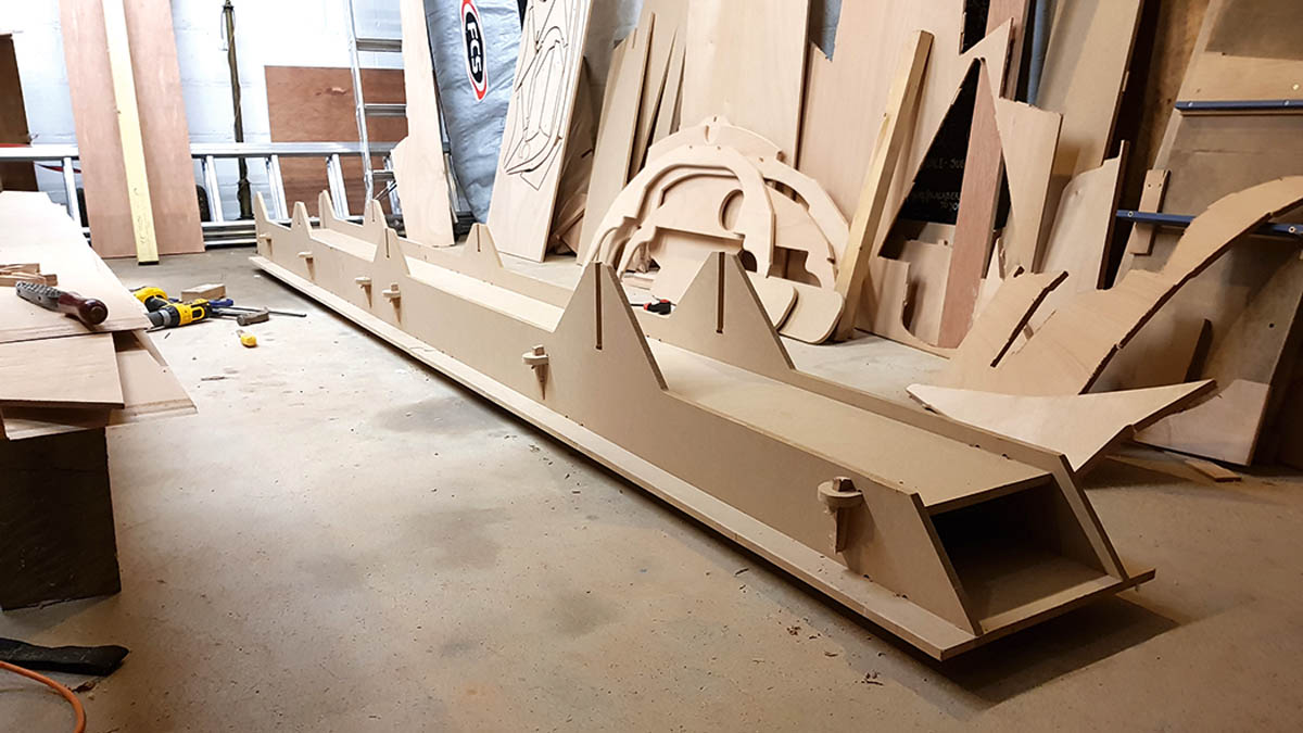
7. The assembled jig, the right way up. The lugs are locked in place using a simple but ingenious system of wedges.
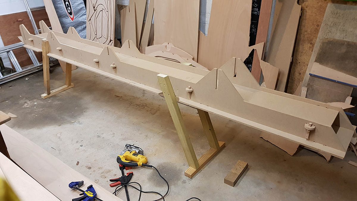
8. Jeremy improved on the basic jig by adding legs to raise it to a better working height. He suggests it would be even better if some diagonal braces were added to the legs to stiffen them up.
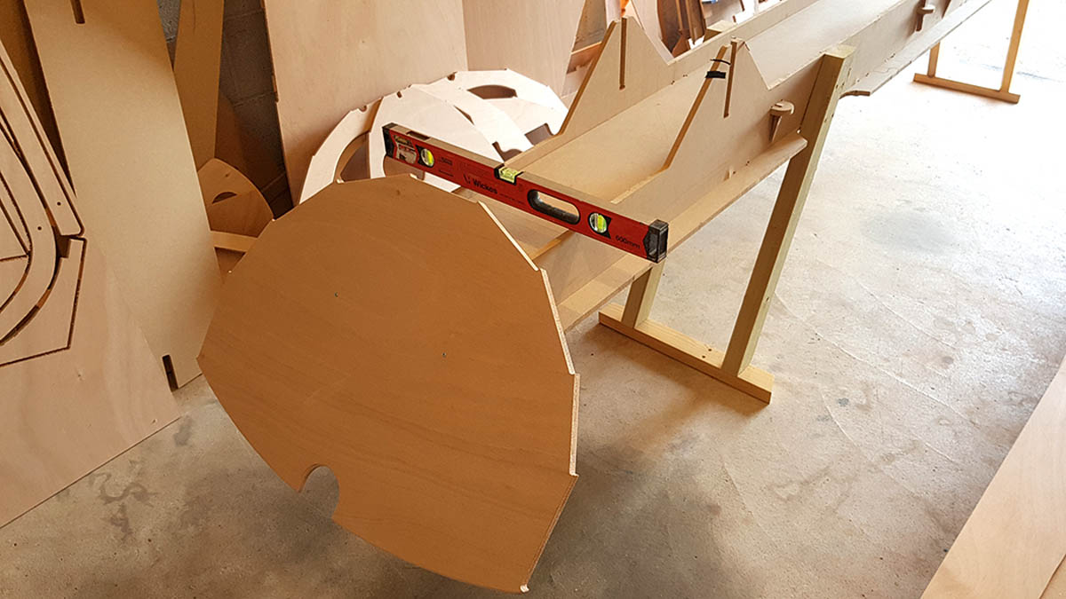
9. A rectangular block screwed to the inside of the transom is used to locate it. Note the flat ‘lands’ precut to receive the planks. Unlike traditional boatbuilding, the edges are not bevelled: the gaps will be filled with epoxy instead.
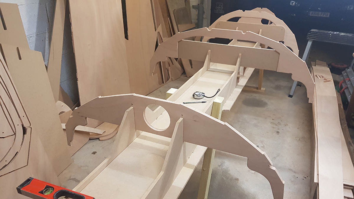
10. The frames all slot into the jig. The hull is shaped by the frames alone, which remain a permanent part of the structure. Note: the building jig and frame alignment method differs on the set of plans and instructions on pbo.co.uk
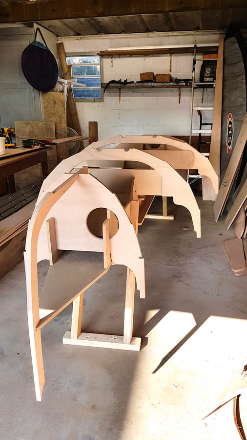
The apron (or ‘inner stem’) is locked in place between the jig and the forward frame/bulkhead. Everything is in place, ready to receive the bottom board. Note the limber holes precut on the undersides of the frames.
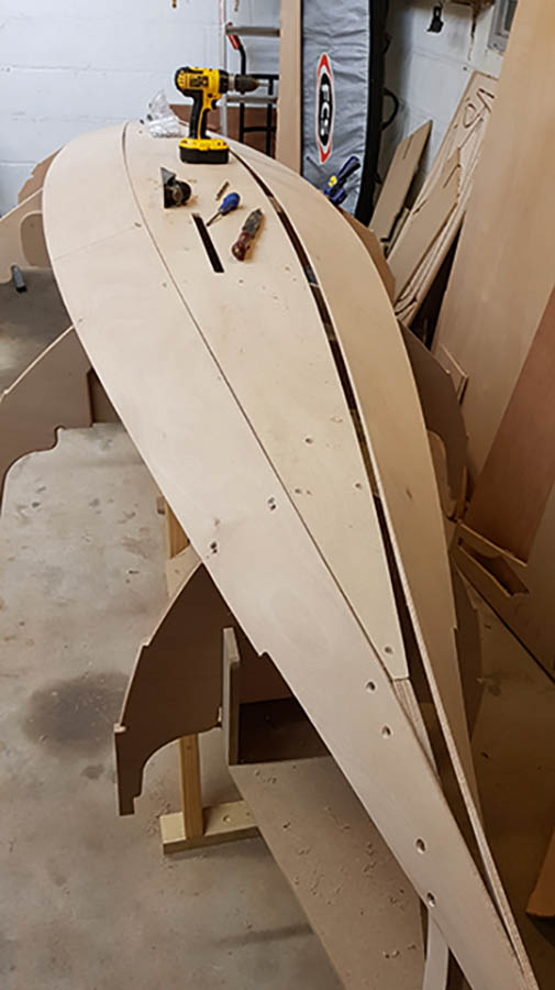
12. The bottom board is in place, and the garboard planks are being offered up. This is the hardest plank to fit, as there’s considerable twist where it meets the apron.
About the builder
 After a childhood messing around on boats in Cornwall and the south of France, Jeremy Butler decided he was going to be a fisherman. He worked on oyster boats on the Carrick Roads, longlining off Newlyn before fetching up at the Falmouth College to study Small Craft design. He eventually decided to study Psychology at Essex University, but spent most of his time building dinghies for Barrow Boats on a piecemeal basis, getting paid £300 per boat. After a formative year out in Australia, he retrained in IT and has been working in software ever since.
Jeremy explains his reasons for wanting to build a Western Skiff: “Living so close to the river, so I want to get out there and enjoy it with the family. I love rowing, and I’ve already built a strip-plank canoe, but that’s a bit tippy for the family. I’d love to build a Whitehall skiff, but I think that might not be very practical for the kids either. I want something I can enjoy rowing on my own but that the family can all pile into and explore the river, so the skiff ticked lots of boxes.
“My idea is to build the boat light enough to stick on the roof of our car. I don’t want to have a trailer or a cover. I’m going fit a removable wheel on the front and a couple of handles on the back and see if the Barrow boat idea works!
“There’s not a single step between our house and the river, so I should be able to walk down and be on the water in about 5-6 minutes.
“My life is about low maintenance, low grief; I can’t cope with any hobbies that require too much kit.”
How to get free plans
How to turn free plans into plywood parts and templates
- A set of PDF plans (excluding the sail plan and outboard conversion) for personal use only is available free of charge, but please, please don’t forget a small donation to the Ed Burnett memorial fund: justgiving.com/fundraising/bill-burnett1
- The 39 pages of plans (size ‘A zero’) should be printed (black & white is fine; printing firms are available online).
-
Once printed, join together individual sheets by matching the corresponding numbers in each corner and aligning the target marks.
-
Affix the templates directly onto plywood sheets (2440mm x 1220mm / 8ft x 4ft), aligning the edges and you are ready to cut the parts. We estimate
- 4 1/2 sheets 6mm ply
- 1 sheet 9mm ply
- 1 sheet 15mm ply
- 1/4 sheet 12mm ply
- 2 sheets 12mm MDF
- Solid timber (eg. 1in Douglas Fir) for thwarts, etc
Instructions for free Western Skiff plans – click here to download
Overview pdf of Western Skiff plans (10 pages of A4) – click here to download
Full set of pdf plans of Western Skiff (39 pages of A0) – click here to download
Rig dimensions & sail plan – click here to download
Building an outboard well during skiff restoration in 2015, by Nic Compton