
Off with her head! PBO’s Ben Meakins undertakes the process of removing and replacing the cylinder head of a Yanmar 1GM10 engine, step by step

I’m no mechanic, but even I could tell that when my Hunter Impala Polly’s Yanmar 1GM10 started losing revs and chucking quantities of black oil out of the exhaust, something fairly major was wrong. This brought on one of those periods of deep despair that only a large, looming engine bill can engender in the mind of a cash-strapped boat owner.
However, some research revealed that a common problem on these engines occurs when the inner jacket of the exhaust elbow corrodes through, resulting in hot, salty exhaust water being injected directly into the exhaust port on the cylinder head.
The general consensus was that on an engine this size, removing the cylinder head was a relatively simple job. Doing so would allow me to check for corrosion, clean out any build-up of carbon in the exhaust port and take the head to an expert to inspect it properly for damage. I was lucky in that the installation on Polly allowed full access to the top of the engine – on some boats, the engine would have to be removed.
Doing the fairly straightforward yet time-consuming removal and refitting of the cylinder head myself would save me having to pay a substantial amount for a mechanic’s time, leaving only the parts cost: not insignificant by any means, but a fixed price at least.
A good workshop manual was essential. You can buy them online from Yanmar dealers and eBay. Some are available to download for free from www.motoren.ath.cx.
Step 1: Removing the head
I had prepared the engine beforehand by removing the negative battery cable, draining the cooling system and taking off the alternator.

1 I undid the hose clamps and removed the water hoses from the exhaust elbow and thermostat housing.

2 Next, I removed the exhaust elbow from the engine by undoing its three retaining nuts.

3 I disconnected the lower water hose from the thermostat housing, before removing the wire terminal from the water temperature sensor.
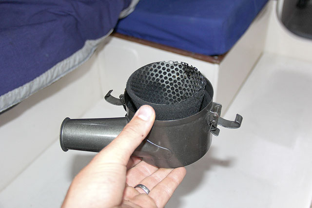
4 The air filter is held in place by three clips. Removal reveals a base plate which can then also be taken off.
5I next disconnected and removed the injector. The manual recommends removing the pre-combustion chamber at this stage, but I couldn’t shift it so opted to do so on the bench at home.

6. With its single retaining nut removed the valve cover could be lifted off.

7 Now I could remove the rocker arm stand retaining nut and rocker assembly, taking care not to lose either of the arms or dislodge the percussion caps on the valves.

8 Now the pushrods could be removed. I used tape to mark them temporarily so I could be sure they’d later go back in the same place.

9 There is an oil line banjo fitting at the rear of the cylinder head, seen here behind the air filter base. I disconnected the oil line, taking care not to lose the washers.

10With all the ancillaries removed, I could undo the cylinder head retaining nuts in a diagonal pattern, before lifting off the cylinder head and old gasket.
2. Checking for damage
With the head removed, it was time to clean up and take stock. I took the cylinder head and elbow to Marine Power in Bursledon, the local Yanmar dealer.
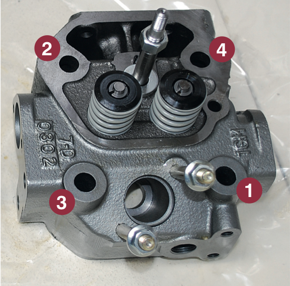
Here, Pete checked out the damage with an expert eye. With a small screwdriver, he pointed to a large hole in the exhaust elbow’s inner tube – and, unfortunately, a corresponding hole in the wall of the cylinder head. ‘I’ve not seen many this bad,’ he said. That explained where the oil was coming from – straight from the pushrod space to the exhaust. Luckily, he explained, I’d caught
it in time: hot exhaust water inside the engine block for a prolonged period would have been more terminal.

The old cylinder head (left) had to be replaced with a bright, shiny new one
It is sometimes possible for a hole in a cylinder head to be welded up, but on the Yanmar 1GM10 the cast-iron walls are thin and welding could have an uncertain result. Therefore, following a call to Polly’s co-owners we bit the bullet and, with wallets significantly lighter, left with a new cylinder head, exhaust elbow and head gasket, ready to fit.
A new head for the 1GM10 comes with a set of valves – just as well, as the old exhaust valve seat was looking a bit pitted – but it was possible to reuse some of the parts attached to the old head.

The thermostat housing is held in place by just two bolts
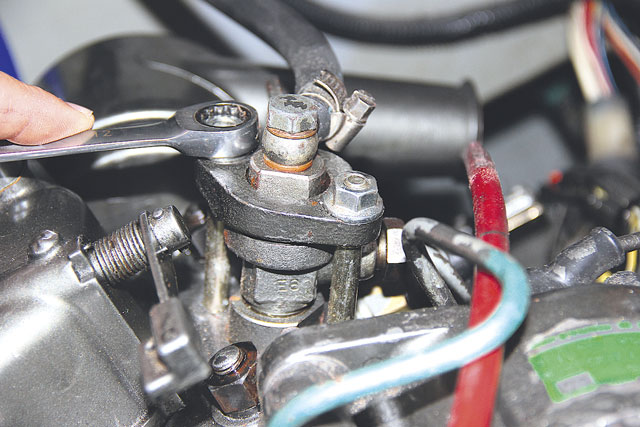
The thermostat housing, temperature sensor and pre-combustion chamber could all be used again, so I set about removing these on the bench at home. The thermostat housing was a matter of removing two bolts. The temperature sensor unscrewed with some persuasion from a spanner and long extension bar, but the pre-combustion chamber, sitting at the base of the injector, needed more force. It eventually came free with the use of a softwood dowel and a large mallet.
Step 3: A thorough clean
If you are reinstalling the old cylinder head it will need a good clean in solvent, and the cooling passageways will require blasting out with compressed air. However, as I was replacing the whole head, cleaning efforts could focus on the engine block itself.
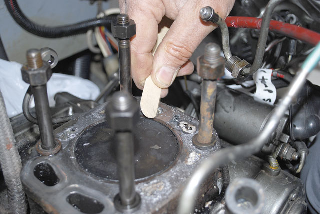
1 I used a softwood scraper to carefully remove the residue left by the old head gasket – a flat metal scraper or wire brush would shift stubborn bits but require care not to scratch the block surface.

2 I cleaned the carbon off the piston top, removed calcified deposits from the cooling passages, then used a vacuum cleaner to suck out all debris.

3 I could now check the studs for damage, and ensure they were fully wound into the engine block. It’s important to ensure the threads are clean and clear.
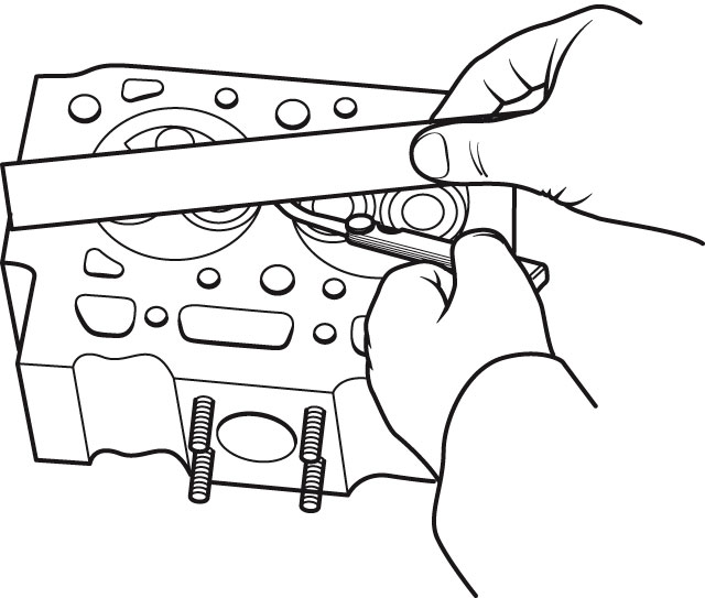
4 Using a straight-edge and a feeler gauge, I checked the block surface for any warping which might affect the gasket seal. If you don’t need a new head, the manual advises measuring diagonally and end-to-end along its mating surfaces, and that any gap should not exceed 0.07mm (0.003in). Mine was OK as it was just out of the box, but if your cylinder head’s measurements exceed this figure, it will need to be resurfaced – and that is definitely a job for the machine shop.
Step 4: Replacing the head
With the mating surfaces scrupulously clean, I could begin to fit the new head. This part of the job is essentially the reverse of the removal process.

1 Ensuring the block and head faces were clean, I placed the new head gasket onto the block. You’ll know which way up it goes: its upper face should be marked ‘top’. Then I carefully lowered the cylinder head onto it.
2 I applied oil to the threads on the studs before installing the spring washers and nuts, and tightening them in three stages – in the sequence shown – down to a torque of 75Nm.
3 Next came the oil-line banjo fitting on the back of the cylinder head – the one behind the air filter. According to one mechanic I spoke to this is apparently often overlooked – so don’t forget it!
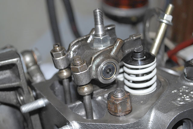
4. Next, the pushrods could be dropped back in their original positions and the rocker assembly relocated. Until all is in place the rocker arms have a tendency to slip from their pivots and the percussion caps try to jump off the valves, so care is needed. Once in place, the rocker assembly retaining nut could be tightened to 37Nm.

5: I installed the pre-combustion chamber, formed from a number of components sandwiched by copper washers and a fibre heat shield. With this slid into place the injector could be inserted and clamped, and its fuel line reconnected

6 The air filter’s base could then be re-bolted to the rear of the engine, the air filter clipped back on, and the wire lead to the water temperature sensor reconnected.

7. Here’s my new exhaust elbow and gasket being fitted, and after that I moved on to the water hoses on the front of the engine.

8 The exhaust hose and water injection hose could then be connected to the exhaust elbow.

9 I refitted the alternator to the engine and tensioned its belt. Being able to just twist the belt through 90° is typically correct.

10 Finally I had to adjust the valve clearance. With the piston at top dead centre (there is a mark on the flywheel and a viewing hole in the flywheel case), I adjusted the locknuts on the rocker arms so that a gap of 0.2mm (0.008in) existed between the rocker arm and the valve percussion cap. With the valves adjusted I could refit the valve cover with a new gasket.
What it cost: (2013 prices)
Cylinder head, new: £600
Head gasket £55.02
Exhaust elbow £180.80
Exhaust elbow gasket £6.89
Thermostat housing gasket £2.14
Air filter base gasket £2.14
Total £846.99
Was it worth it?
With the batteries reconnected and the engine seacock turned on – and with no engine bits left over! – the motor started first cough and ran faultlessly thereafter. If your boat has a Yanmar 1GM10 – or indeed, any engine – you should remove the exhaust elbow on an annual basis, clean out any carbon deposits and check carefully for corrosion. For the minimal cost of an exhaust elbow gasket each year, this simple maintenance and inspection procedure could save you a large bill!
Warning
I consulted with a marine engineer when unsure of any step and, with care, was able to successfully refit the head. If you’re in any doubt, calling in the professionals could save you from
making expensive mistakes.