
How to install an Automatic Charging Relay on board to upgrade charging two battery banks - a step-by-step guide

The elderly Vetus battery switch on my boat had become unreliable – especially the ‘make before break’ aspect of it, which had begun to lose connection as you moved the switch from one battery to another.
I originally looked for a replacement switch – if it ain’t broke – but then began to think of updating the system. In the past few months I’d left the batteries on for a fortnight when leaving the boat, and having someone jump down the companionway to change the batteries over when we wanted to start the engine was a pain.
 I settled on a Blue Sea Systems mini ACR (automatic charge relay), which came packaged with a switch, called ‘mini Add-a-Battery’ for alternators of under 65A – mine is a 35A alternator.
The wiring looked quite straightforward, and the existing wires would hopefully just bolt straight on to the back of the switch. I’d need to make up new, fused ones for the ACR. The system has an optional ‘start isolation’ wire, which can be connected to the start button. This isolates the house batteries from any loads or spikes from the engine as it starts, and seemed a good idea for a few minutes’ extra work.
With the system installed, all looked good – until I realised that the heater took its power from the back of the engine’s power supply. This of course meant that the heater would now be drawing its current from the now isolated starting battery – not ideal. I ran a wire forward to the battery switch’s accessories terminal – problem solved.
Here’s how I wired it up step-by-step

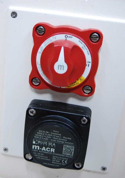
1: This was the original Vetus battery switch, mounted on the side of the bunk seat that houses the boat’s two batteries. I decided to replace it with something more modern and less susceptible to human error.
2: I removed the old battery switch and made up a painted plywood panel with holes cut out for the battery switch and ACR and mounted it on the side of the battery box.

3: Next, I wired up the battery switch. This has four teminals on the back: one for the accessories, to which I also connected the heater, and one for the house battery’s positive cable. On the other comes the engine start/charge cable and the start battery’s positive feed.

4: Next up came the ACR’s wiring. This consisted of a wire to the positives of both house and start batteries.
These should be of a cable size sufficient to withstand the full charge of the alternator as the batteries are linked, and should be fused – for my alternator these needed to be 60A, and I went for 16mm2 cable for safety.

5: I used a pair of 60A midi fuses between the ACR and the batteries, using 16mm2 cable with crimped ring terminals to make a safe and heavy-duty set-up for each one.

6: A ground wire went from the negative bus bar to a spade terminal on the back of the ACR via a 10A fuse. The other terminal was connected to the push-start button on the engine control panel, making sure that it was the terminal that is live only when cranking. This isolates the house battery loads from the engine to avoid voltage spikes and drops when starting the engine, should a high float voltage trick the ACR into combining the batteries when the engine isn’t running.

8: And that’s the wiring completed. With this, the switch and ACR are successfully installed. When the ACR detects a charge on either battery, it combines them after a two-minute delay, and when the charge stops, it isolates them.
Wiring Diagram:

Checking the operation of the VSR
 An LED indicator on the front of the ACR shows its status. You can check the operation of the unit with a multimeter. With the engine off, the house battery is 12.39V and the start battery 12.65.
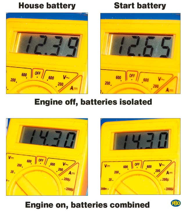
With the engine running, you can see that both batteries are charging at 14.3V. The boat’s battery monitor shows that starting the engine does not affect the house batteries.
I’m really pleased with the new system – you can safely start the engine whenever you like without having to worry about switching the batteries over, and it’s really reassuring to have the start battery ready for action.