
Chill out with David Rainsbury by following his step-by-step guide to converting a coolbox into a fridge

Built in beneath the navigator’s seat of Kate, my Vancouver 274, was a boat coolbox, which is very useful if you can get ice or find some means of having your ice packs refrozen. But on a long trip, especially to warm places, this simple approach can be an unreliable means of keeping food fresh and the gin and tonic cold.
Aboard my last yacht, Piper, a Contessa 26, I used a 12V coolbox, but it proved very heavy on battery drain and could only really be powered up when the engine was running.
With Kate heading for France and the north coast of Spain I decided she needed a proper fridge. Converting the existing coolbox to a boat fridge by the addition of a compressor and evaporator plate kit proved to be a simple project.
Choosing a unit
First I had to know how big a space I wanted to cool. Fridge kit capacities are generally quoted in litres, and using metric units to calculate the volume is very simple. You need to measure the length, width and depth of the cooling compartment in centimetres.
The volume in litres is:
length x width x depth (cm)
/1,000
Kate’s coolbox worked out at just under 30lt. The Isotherm kit I chose had a capacity of up to 80lt and was about the smallest available, so at least it wouldn’t be overworked! The evaporator plate would fit on one of the larger sides of the coolbox with a margin all round of about 2cm. Designed for easy installation, the kit came with most of the bits needed to complete the job.
Siting the compressor
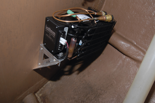
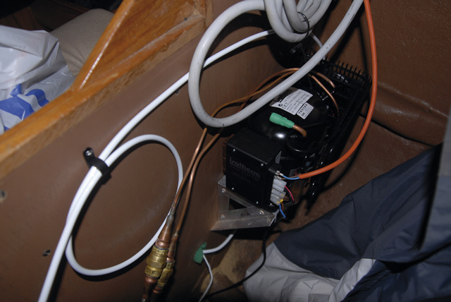
The compressor unit in place on the bracket and ready for connection
You need a location close to the coolbox that is dry and has a good circulation of air.
Immediately behind the navigator’s seat aboard Kate is the wet locker. This space extends out below the side deck, well clear of any hanging oilies, and is space that would otherwise be unused. This was the perfect place, close to the power supply and with a stout bulkhead for mounting. As a side benefit, when it’s running the compressor unit’s fan will circulate the air in the locker.
Mounting the compressor unit
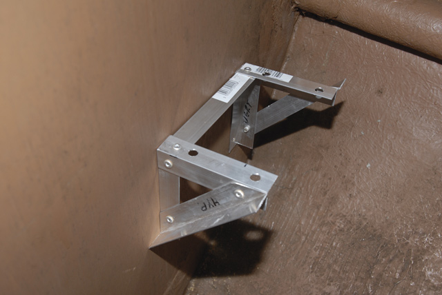
The compressor support bracket, fabricated from aluminium angle section and screwed to the bulkhead inside the wet locker
For sound insulation the compressor unit has feet isolated from hard contact with the supporting surface by rubber pads. There is an 8mm diameter hole through each rubber pad, designed for locating the unit. Working to the positions of these holes I designed a bracket to fix the compressor to the bulkhead and from a DIY supplier I bought a length of 40mm aluminium angle. The bracket was fabricated using pop rivets and then screwed to the bulkhead using stainless steel woodscrews. The compressor unit is held in place on the bracket by four 8mm diameter bolts, passing through the holes in the rubber feet and fastened with Nylock nuts.
The nuts were tightened sufficiently to hold the compressor unit firmly in place, but not so tight as to compress the rubber feet. Penny washers sat below the bolt heads to spread the load across the top surface of the rubber.
Cutting the pipework hole
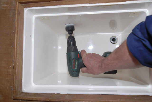
I used a hole saw to cut the hole for the refrigerant pipework
Two large self-sealing couplings join the pipes running between the evaporation plate and the compressor. To pass these through from the inside of the coolbox to the wet locker required a hole of 35mm diameter and the tool to cut the neatest hole of this size is a hole saw. Holding the evaporator plate in position inside the coolbox I marked the position of the hole.
Beginning work on the inside I cut to the full depth of the hole saw. This took out a disc of the GRP coolbox and a plug of the foam insulation. With a total depth of hole of nearly 150mm (6in) it took several ‘plugs’ to get all the way through.
Before the guide drill broke through on the other side the chuck of the drill came up against the hole in the coolbox, so I could go no further and needed to start working from inside the wet locker. I fitted a long, small-diameter drill to the chuck and drilled a pilot hole right through from the coolbox to the other side of the bulkhead. The bit was intended for masonry but was plenty long enough and made good, if slightly smoky, progress through the ply bulkhead. Due to their combined length I had to insert the bit in the hole first and then attach the power drill once it was in place – but at least I then had a pilot hole to work from the wet locker side of the bulkhead.
I refitted the hole saw, centring the guide drill on the pilot hole and completed the task of cutting the hole without further problems.
Fitting the evaporator plate
Marking out the fixing holes for the evaporator plate is complicated by the presence of the pipework, but as the holes are at the corners and symmetrically placed I was able to reverse the plate and, with the pipes on the ‘wrong’ side, mark through the holes. The plate is held in position by four self-tapping screws, with plastic spacers holding it at the correct distance from the side of the box.
The thermostat probe attaches to the evaporator plate on the side closest to the side of the coolbox. The control knob can be fitted on the inside of the box but as I had chosen to fit mine outside I had to thread the probe through from the wet locker before using the small bracket to fix it to the evaporator plate.
With the screw holes drilled, the pipes need to be carefully unrolled and threaded through from the inside of the coolbox, gently lowering the plate into position. The pipes are soft copper. Bend them to a gentle radius as they enter the hole, taking care not to kink them.
Once the pipes are sitting comfortably, not fouling the edges of the hole, the plate can be screwed in position, not forgetting the spacers between the plate and the side of the box.
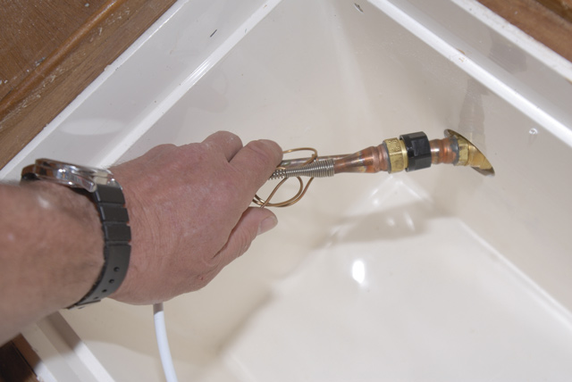
Pass the couplings through from the inside of the coolbox, taking care not to kink the pipes
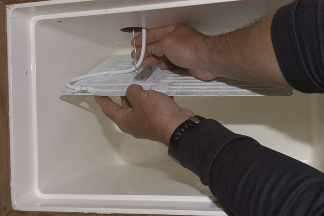
Carefully feeding the refrigerant pipe through from inside the box as the plate is positioned. Note the gentle curve in the pipe and the thermostat probe fixed in position on the plate
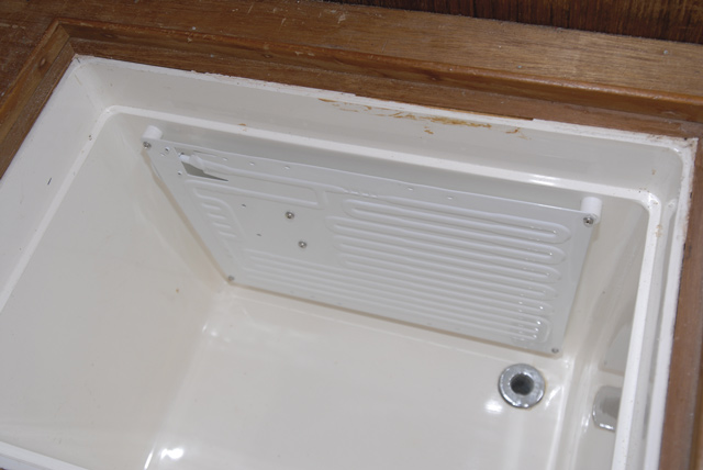
The evaporator plate fitted on the larger side of the box, with a margin of about 2cm all round
Connecting the pipes
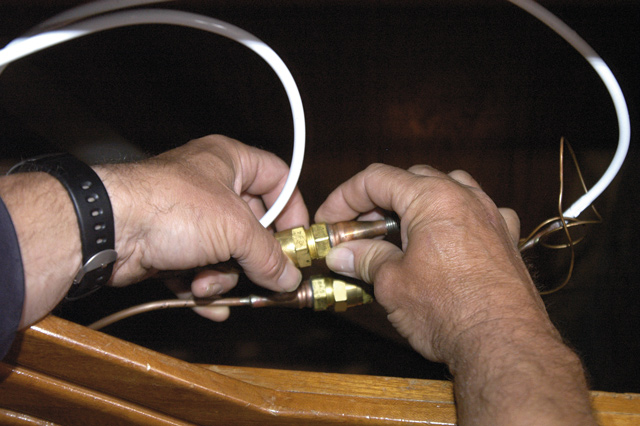
Connecting the refrigerant pipes. Only one side of the connection will turn, the other must remain fixed
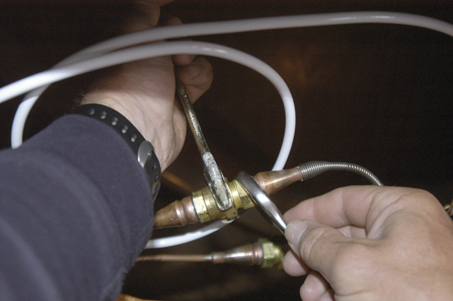
Tightening the refrigerant pipe connection, taking care only to apply torque to the movable part of the joint
Connected and almost ready to go. The surplus pipe is coiled neatly and fixed securely
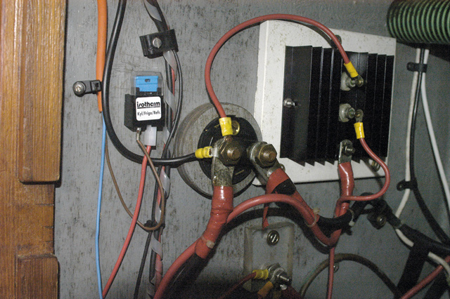
An inline fuse is wired between the positive supply and the thermostat/switch
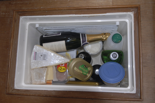
Fresh food and cold drinks can now be kept on board thanks to the new fridge
I gently bent the refrigerant pipes so that the couplings met in line and so that the excess pipework was neatly coiled with no sharp bends and in a position in which it could be firmly supported later.
The refrigerant pipes have couplings with a male and female thread on each part so that they cannot be connected the wrong way. Only one side of each complete coupling will turn, the other is fixed. It is essential to hold the fixed part still, turning only the part that is free to rotate in order to screw them together. Once the joint has been tightened up securely use clips to secure any excess pipe so that it cannot vibrate or get in the way.
The pipes emerge from the coolbox through quite a large hole. This should be sealed with insulating foam. I used a plug of polystyrene packaging, carved to shape with a craft knife and cut along its length to slip over the pipes as it was pushed into place.
The power supply
The manufacturer specifies that the fridge unit should be wired directly to the supply battery. However, I wanted to ensure that the fridge would also be switched off when the yacht’s power was shut down. I connected the negative wire to the negative of the battery bank, and the positive I wired to the service side of the main isolator switch. An in-line fuse, supplied with the fridge unit, is in the positive line between the isolator and the fridge switch unit.
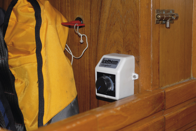
The thermostat/switch in position inside the hanging locker behind the navigator’s seat
How well does it work?
The total cost of the project was a little over £300. As my partner Kathy pointed out, a new fridge at home, complete with cabinet, doors and shelves costs slightly less than the bare working parts for this one.
I stacked the fridge (née coolbox) with all the good things in life that it would now be possible to keep aboard. It would be more efficient if kept full. Most of these things, the milk, fresh meat and cheese were already cool from the supermarket. I then switched on the power after first checking the state of the domestic battery, which was well charged at 13.5V.
With a mains supply on hand for recharging batteries, I set the thermostat at about half power (three, on a seven-point dial) and let it run all night. It was very quiet so I couldn’t tell how much it was running. By morning the 80Ah domestic battery was down to just over 12V, but had also been powering the lights and other domestic stuff, so the drain was fairly modest. I was looking forward to cold milk on my breakfast and opened the lid with eager anticipation. The milk, which had been standing right next to the evaporator plate, had been frozen solid.
So that at least proved it is efficient!
I next set the thermostat at its lowest level. Maintaining the contents well chilled but not frozen the compressor runs for about half a minute every 10-15 minutes whilst the fridge is full and the lid remains closed. With the large solar panel on deck I can almost discount the current drain. I’m looking forward to enjoying the new fridge’s benefits during Kate’s summer cruise, not just the cold beer, but a greater range of fresh produce that I can now buy two or three days in advance.
Insulation
I was greatly assisted by the fact that my coolbox was already well insulated with at least 100mm (4in) of injected foam insulation all round, in addition to the 15-20mm (5⁄8-3⁄4in) ply that the outer casing is made from. The better the insulation the more efficient the fridge will be and the less energy it will consume.
David Rainsbury is an Ocean Yachtmaster with more than 20 years’ experience, mostly sailing from his base in the Menai Strait. He has sailed single-handed as far as Bergen in the north and the Loire in the south, as well as the entire coastline of Britain and Ireland.