
Olly Epsom explains how (and why!) he built his own 1kW DIY electric outboard motor for under £600...

For most people, building a DIY electric outboard motor is unnecessary, time consuming, and may well result in a product that is both inferior to, and more expensive than a new commercial electric outboard.

It will almost always be possible to buy a petrol outboard for less. So why did I do it? Well, my motivations were as follows:
1. To keep myself occupied at home, alone, over the long nights of a Scottish winter (over previous winters I’ve constructed a navigation system, an autopilot and solar water heaters).
2. Because I wanted a system that was more powerful than the cheap trolling motors, but much cheaper than equivalent commercial units (an equivalent ePropulsion Spirit currently retails at around £1,500)
3. Because I have longer-term aims of making the system fully remote controlled (essentially a drone, perhaps for wildlife photography), and for that I needed complete mastery of the control system, which is achievable if I build it myself.
There may be other reasons to embark on such a project, and if so, fill your boots.
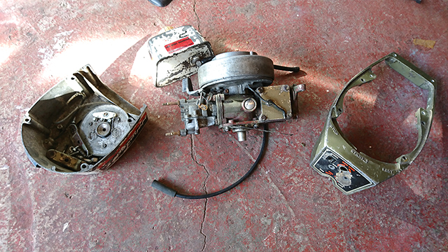
Unused petrol engine parts
Preparation and design
To embark on a project like this requires a basic knowledge of electronics and mechanics, but should be within reach of most practical people with a willingness to learn.
The voltages are low enough that they should not present an electrocution risk but take all appropriate precautions when working with electricity and moving mechanical parts.
My project utilised computer control and a lot of new-to-me equipment such as touch screens, Bluetooth, Arduinos and oscilloscopes.
I also had to learn how to code the software.
With the learning and setbacks the project took me about six weeks of evenings.
You may wish to structure your project differently – a significant simplification could be made by discarding computer control.
I had the rough design in my head after an evening of research online.
I decided to use the bottom end of a conventional, second-hand outboard motor as the basis of the machine.
Above this, in place of the engine would be an electric motor, directly coupled to the driveshaft. Electronic control systems would be mounted alongside the motor.
The battery would be separately mounted and connected via flexible electric cable.
I settled on a power of about 1kW because it is significantly more than two rowers could achieve and would result in either a fast dinghy, or a dinghy with significant reserve power.
Batteries cannot be fully discharged without damage, so to power this for a minimum of 40 minutes at full power would require roughly 1kWh of batteries.
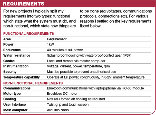
Propeller and drive are to be retained
Components
The motor, control systems and batteries are the main components, but figure on another £100-£200 to cover enclosures, transition pieces, wire, switches, connectors, and, of course, things going up in smoke.
This will bring the total budget to around £500-£600.
Plus weeks of your time. Suddenly rowing may seem less of a hardship!
But I am single (hard to believe I know!) and live alone and have nothing better to do with my time and money so onwards I went.
I located a 1974 Johnson 2hp outboard on ebay for £24. It cost me more in fuel to collect it.
I removed everything north of the driveshaft housing and re-sold those components for £5.
These old engines had very high specification mechanical components and the gearbox in particular was in excellent condition.
That said, the motor was forward-speed only, with no clutch.
It is possible to make an electric motor go backwards as well as forwards but be cautious doing this on an engine which originally had no reverse because the gears won’t be designed to operate backwards and there won’t be a thrust bearing to keep cogs in check.
I decided on a brushless DC motor because they are generally reliable and don’t require maintenance of brushes.
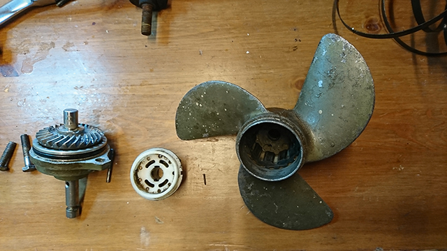
Original cooling impeller can be discarded
Usually they are slightly more efficient than permanent magnet DC motors as well, although in practice this depends entirely on the specific motors being compared.
Most motors in this power range run at 48V or above. While it’s possible to get 12V motors in this power range, they would draw over 90A at full power, requiring unacceptably heavy wires.
In addition there was a far wider range of motors available at 48V.
Likewise battery packs at 48V were more numerous. I settled on lithium-ion batteries due to their high capacity, low weight and high cycling ability.
A 1kWh lithium battery is roughly 20Ah at 48V – about the same amount of energy held in an 80Ah car battery at a quarter of the weight.
The downside to lithium-ion is the cost. There are various battery packs on ebay and Alibaba.
All have a built-in charge controller, and all require an external mains charger.
Batteries of this capacity range from £200-300 depending on vendor, delivery charges and taxes. The vendor also sold me a ‘matched’ charger which subsequently caught fire.
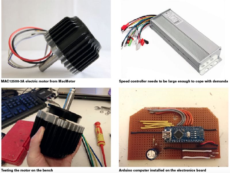
It would be very nice to have a high specification Parvalux or Maxim motor, but these things come at a significant cost, so I settled for a Chinese-made MAC12500-3A from MacMotor.
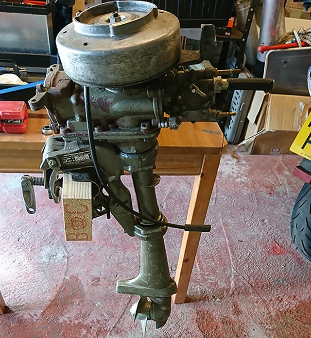
Scruffy, but well-built 1974 2hp Johnson
This is a 48V, sensored brushless DC motor with a top speed of around 4,000rpm and a power of 1kW, and it seemed like a reasonable match with the donor outboard’s original specification delivering 1.49kW at a top speed of around 4,000rpm.
MacMotor also sent me a speed controller, although that later proved to be less than spectacular and I had to replace it with a larger model.
The motor was around £100, the speed controller another £40.
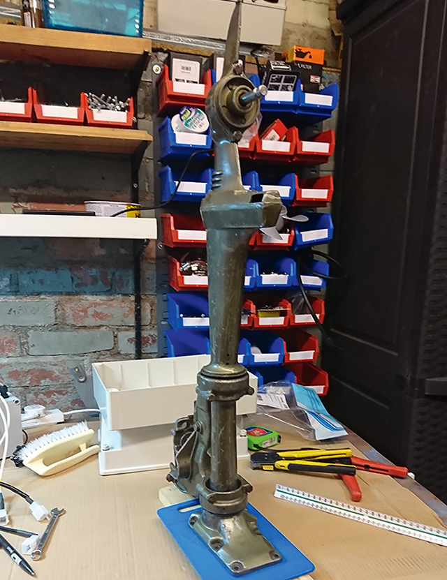
The old outboard motor stem
Arduinos are tiny programmable computers with analogue and digital inputs and outputs. They run on 5V, consume an infinitesimal amount of power, and are of an inherently rugged, tough and reliable design.
They are programmed from a PC using a language derived from C (you’ll need to know a bit about programming to know what that means). They come in various models including the Nano that costs just £3.
While simple, they are more than powerful enough for a task such as this.
As a display I initially intended to use a cheap, rugged, reliable two-line, 16-character LCD display of the sort that are well known to work with Arduinos.
I then noticed the Nextion range of graphical touch screen displays, which retail at around £16 for a 3.2in version.
Whilst not as rugged or tough I was seduced by their sexy colour screens, with the ability to display multiple dials, graphs and buttons.
Finally I located a cheap electric bike twist-grip throttle for around £10 on ebay.
The one I bought came with a battery voltage indicator and miscellaneous switch that I figured might be useful.
Mechanical assembly
The project was constructed in my garage with hand tools.
That said, the better equipped your workshop the better the finished product is going to be and, in addition, costs will reduce because I had to have a few parts manufactured that could be made at home in a good enough workshop.
At the bare minimum you’ll need a good toolkit, hacksaw, files, drills, power/battery drill, lighting, workbench, soldering iron and good multimeter.
An oscilloscope is also useful, I used a PicoScope USB-type that plugs into my laptop.
The first hurdle was to mechanically connect the electric motor to the donor outboard engine. This connection needs to be secure and accurate.
I measured up all mounting holes on top of the engine, and the mounting holes on the electric motor, and sketched up a suitable transition plate on the free online CAD software Onshape.
I then sent this to a laser cutting company, who cut it out of 10mm thick aluminium for around £25. I could have sent it for 3D printing out of plastic.
To connect the motor to the driveshaft I asked a friend with a lathe to turn down the end of the approx 11mm spline and put an 8mm thread on it.
I did consider collet-type connections or finding a matching female spline but the lathe option was easiest for me.
The main disadvantage of this, however, is that every time the motor is removed it brings the driveshaft with it, which makes reassembly quite a faff.
The lathed spline screwed nicely into the 8mm female thread on the motor shaft, and a lock-nut completed the union.
At this point the motor, donor engine and driveshaft are all connected, so to avoid accidents with a fast-spinning prop it’s a good idea to remove the propeller and not replace it until you’re going to use the motor in water.
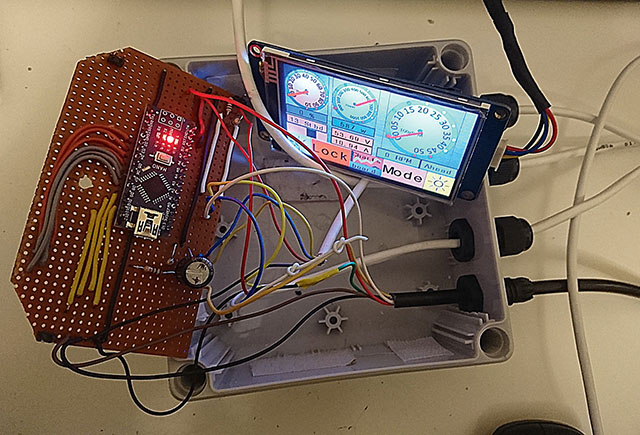
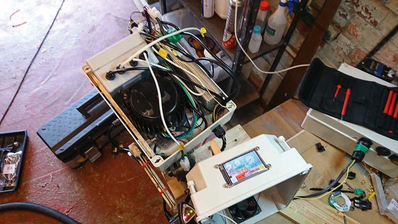
Testing the assembled electronic components on the bench
Electrical assembly
You’re now able to electrically connect the components and conduct a simple test.
1. Connect the three thick phase wires from the motor to the appropriate colours on the motor controller. These are usually coloured green, yellow and blue.
2. Connect the sensor plug on the controller to the sensor socket on the motor. This will have at least five wires. Usually red and black (5V and ground) and green, yellow and blue (which take the signals from the three hall sensors in the motor). Hopefully plug/socket from the hall sensors on the motor will match the plug/socket on the controller hall sensor line, otherwise go figure it out.
3. Connect the red wire on the throttle to 5V (usually available on one of the numerous outputs of the motor controller), the black wire on the throttle controller to ground on the motor controller, and the third wire (could be any colour) to the speed input of the controller, which could also be any colour.
Finding which wire does what in a manual-free wasteland is very challenging. Some controllers may not have a 5V supply for the throttle and you may need to provide this separately via a 48V-5V DC converter.

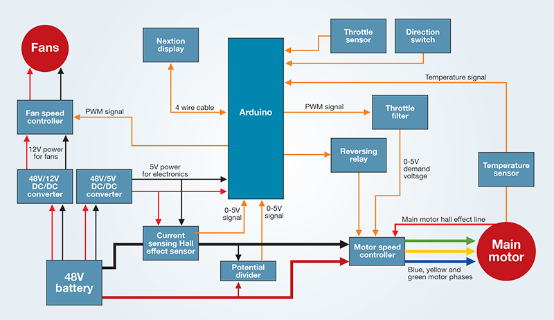
This should not daunt you as they are easily available. In addition most controllers have a reverse function which requires connection of a switch. One such arrangement is shown in the schematic diagram (above) of the simplest possible control system.
Now is the moment of truth. Connect the battery positive and negative to the motor controller positive and negative, and give the throttle a twist.
At this point, assuming the motor turns, you are essentially home and dry. All that remains is as many weeks of refinement as you care to deploy.
And the inevitable problems that emerge, some of which I’ll detail in my next article.
If it doesn’t go check your connections and wiring. These motors hardly ever fail, so if it’s not working it’s most likely the controller and the parts connected to it that are the culprits.
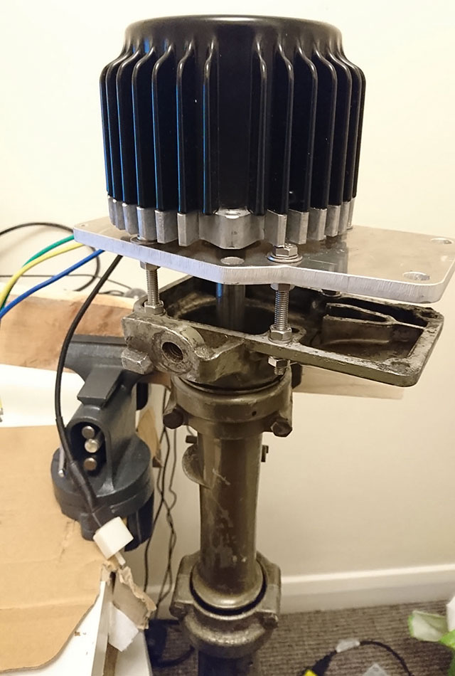
Transition plate and connection between electric motor and outboard leg
User manuals
A word of warning: neither the motor, controller, Nextion display, charger or battery came with a shred of documentation. I used a multimeter and figured it out for myself.
The Nextion display in particular was impenetrable as they hadn’t been around long enough for a comprehensive internet community to form – this is changing for the better.
Part 1: the basics – as published in the December 2018 issue of PBO.
DIY electric outboard motor controller system
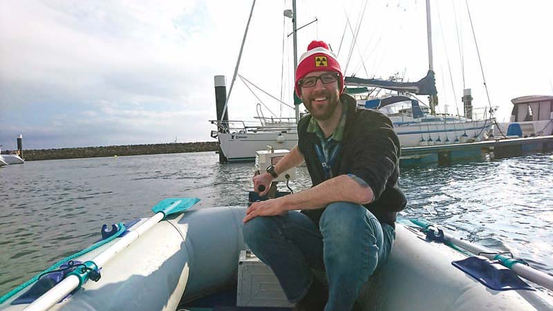
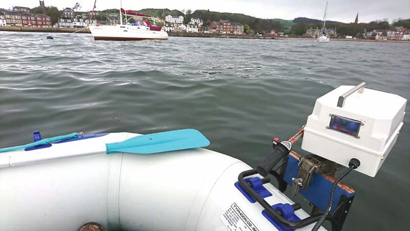
Olly’s electric outboard motor works a treat zipping around Largs
Olly Epsom explains how he designed and assembled the computer control system for his powerful, low cost home-built electric outboard
The setup as detailed in last month’s article is perfectly acceptable. In essence, all I did was to replace the engine block of a 1972 2hp Johnson outboard with an electric motor.
I installed a speed controller, a lithium-ion battery and bought a twist-grip throttle from an electric bicycle outlet online. A simple current/voltage monitor of the sort widely available online will then leave you with a similar setup found in commercial electric outboard units.
But we want bigger, better, sexier, more fun. Well, I did, anyway! Using various low-cost off-the-shelf components I built and tested the following elements:
1) A computer control and monitoring system based on the Arduino computer. Interaction with the computer is via a touch screen display (by Nextion) which includes a key-code lock. Monitoring of motor speed, temperature, voltage and current is performed and displayed. Control of motor speed and cooling fans is provided. In addition there is a facility to control the motor via Bluetooth which is of no practical use but looks cool.
2) A proper enclosure for the motor and battery, which protects the components from the weather.
3) Electrical and mechanical cooling systems following testing of the motor in real conditions. This system consists of four variable speed cooling fans, and one 3D printed mechanical cooling fan directly attached to the motor shaft.
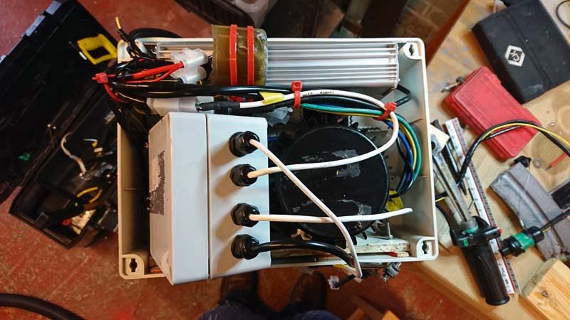
Overhead view of the electric motor with the lid removed
The computer
Adding a computer controller can dramatically improve usability, security and confidence in operation.
The internal workings of all electronic computers are digital, but the real world is usually analogue. An Arduino Nano can monitor up to six analogue inputs, deliver six quasi-analogue outputs and eight digital inputs or outputs.
Analogue inputs: in this case means voltages between 0 and 5V which the Arduino sees as a number value between 0-255.
Quasi-analogue outputs: the technical term is Pulse Width Modulated (PWM) output. Again this is a voltage between 0 and 5V which the Arduino sees as a number value between 0-1023.
Digital input/outputs: There are eight pins which can provide digital inputs or outputs. Digital means discrete, a choice of two values, in this case 0V OR 5V.
Checking out the motor in the workshop after a dunking
Bench testing my DIY electric outboard motor
Construction is under way. The motor is connected, the motor controller wired up, some form of simple computer control may be installed, and the battery is fully charged. In addition fans and sensors may also be fitted.
There probably isn’t a cover or housing, but you can duct-tape everything together, find a suitable piece of water (a canal is excellent) and go for a spin. This I did in February.
The first snag I hit was that the bracket I had for the dinghy was too high, meaning the propeller was half out of the water. The only solution was to sit at the back of the dinghy, which ruined the hydrodynamics.
But the motor worked well, and was fast and powerful. I was averaging 5kph until after just over a kilometre at full power there was a sudden jolt and the motor stopped. “Bugger” I thought.
My first thought was that the motor had seized. It hadn’t, although the base plate was very hot.
Not that surprising given the stated efficiency of the motor as ‘Above 80%’ meant that, at full power, it was dissipating 200W.
I deduced that the motor speed controller had failed, and when I dismantled it at home this did in fact turn out to be the case.
I suspect it was undersized for the motor. I ordered a replacement, more powerful, controller rated at 1500W. When it arrived, it was a mass of unidentified wires and it took me a couple of evenings to identify the throttle.
To this day I haven’t identified the reverse system. I thus have a motor fitted ‘for but not with’ reverse.
Still, this is not necessarily such a bad thing given that the donor motor was never designed to operate backwards in the first place.
At this point I reasoned that there was woefully insufficient cooling fitted. I had a ruffle around my electronics stores and located four 12V fans of various sizes.
How fortuitous that I had a 48V-12V converter to power them!
I connected them to run at variable speed based on motor temperature under Arduino control, but if you don’t want to use a computer, just wire the fans to run continuously.
Also, reasoning that ‘mechanical is best’ and that, at 4,000rpm at full throttle the motor would be turning faster than most DC fans, using the CAD program OnShape I designed and had 3D printed a mechanical fan that I attached to the motor shaft. This essentially stirs the air up and away from the motor base plate.
I also fitted a Bluetooth receiver and pre-programmed the Arduino to take commands from a Python program I wrote on my laptop.
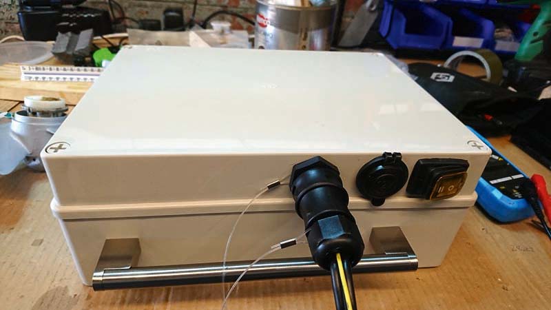
Battery box showing main power outlet. Note stainless steel carry handle from a kitchen unit
DIY electric outboard motor: Refinement and retesting
After the public failure of the first test I wasn’t planning on being caught short again. For the second test I mounted the motor on a wheely bin, filled it with water, and controlled it from my laptop, indoors – it was just after the Beast from the East and there was still snow in my garden.
The computer recorded temperatures, currents, fan speeds etc for later analysis.
This was not needed, because the motor ran for 50 minutes at full throttle without fault. It seemed the bigger controller and cooling systems had done their job.
Why not run it for longer? Because the battery wasn’t fully charged. Why not? Because the charger caught fire. So much for the CE marking…
The supplier immediately sent me a replacement charger but even now I’m loath to leave it charging unattended.
I also cut down the mounting bracket by 150mm, ensuring the propeller is correctly submerged even if the entire weight of a person is not at the back of the dinghy.
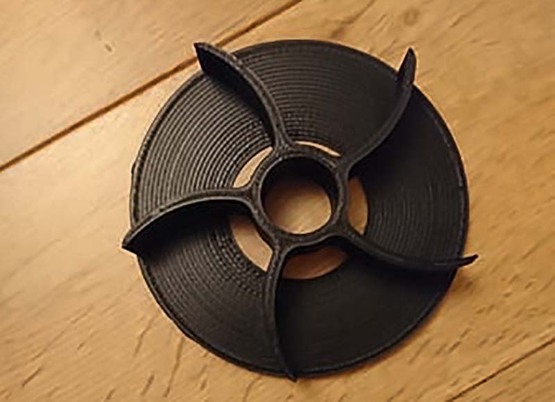
The 3D printed mechanical fan
Enclosure and mounting
Now came the time to properly mount and enclose all your equipment. In my case the Arduino, Bluetooth, and fan speed controller had always been mounted in an IP67 rated enclosure.
For the rest of the engine mounted components (current sensor, potential divider, motor speed controller, fans, throttle sensor, display) a suitable housing was needed.
At first I messed about with GRP but it’s safe to say this isn’t my forte in life, though it’s probably the best route if you are good at it.
Eventually I opted for standard ABS enclosures from CPC-Farnell at around £13 each. One for the battery, and one for the engine.
Since the electric outboard engine is air cooled large holes are needed in the enclosure for the fans. These I covered with aluminium louvres from Screwfix.
The entire enclosure will let water in through the louvres, and out through drains at the bottom, but should protect the interior from deluging.
Since the drive motor and eBike controller are IP55 rated (essentially splash proof) then, provided the entire engine doesn’t go swimming, it should be good to go.
This is where the commercial model outboards have a definite advantage over a home-built one – they can be fully submerged.
Now I realise how much cooling the electronics require, if I was building another I’d consider liquid cooling and a completely enclosed and waterproof motor housing.
It was during the enclosure build that I managed to connect the battery the wrong way around, which blew up the hall current sensor and, luckily, nothing else.
This was my own fault but it’s an example of the sort of thing that happens late at night after a long day.
For the display, I cut a hole in the enclosure to mount it, but used PVC window material (of the sort you get on sprayhood windows) to cover it, which permits use as a touch screen. A 3D printed bezel (again designed with OnShape) then covered the ugly hole and made a more professional finish.
I also used a couple of stainless steel kitchen door handles to mount on the motor and battery box. All fasteners are A4 stainless steel (except they are not of course, most of them are only A2…).
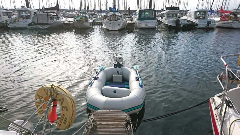
Motor looks pretty neat on Olly Epsom’s dinghy
Mounting to the dinghy is via the donor outboard leg clamp onto a standard bracket
Testing my DIY electric outboard motor
After much frustrating work, testing, building, retesting, rebuilding and swearing, the electric outboard formally entered service in May 2018 on a run from Millport bay to Millport in Great Cumbrae in the Clyde estuary.
Myself and my friend Corey were on the dinghy, and there was a fair swell.
There were a couple of glitches: the 12V DC supply couldn’t cope with the dinghy inflation pump, and there was a minor software error that caused the motor to stop if the reversing switch was pressed.
Seeing the switch doesn’t need to do anything as there isn’t a reverse mode, this doesn’t really matter.
Since the first deployment it has been tested extensively and increasingly aggressively, and has so far given reliable service.
Speed varies with load and conditions but is generally around 3 knots. I suspect that due to motor speed and torque characteristics that the motor could take a larger or more aggressive propeller.
Motor temperature is peaking at about 80°C, which is hotter than I would like, but is not a threat from an electronic point of view.
I programmed the fans go to full power at 50°C and/or when the throttle demand is above 75%. As long as the battery is plugged in the cooling fans will continue to run based on motor temperature.
The key-code lock function means that the motor can be locked with one touch on the display and left safely to cool down.

Running the outboard on a Canadian canoe during a 10km trip on Loch Lomond
One particularly pleasing usage was an endurance test of the motor on my friend Dave’s Canadian canoe on Loch Lomond in June.
The two of us travelled over 10km in under two hours on one battery charge including butting into significant swell.
Not surprisingly the system works better on the canoe than my inflatable, due to much better hydrodynamics, and speeds of 6 knots were possible.
I have also used it to land on Ailsa Craig and, following a clumsy dinghy launch, briefly completely submerged the motor.
The motor continued functioning, although I did have to clear water out of the battery box the next day.
Having used the outboard all summer I have found no serious issues with it and, other than a few minor software improvements (including adding a cruise control function) I have not modified it in any way.
Without wanting to tempt fate, I am fairly satisfied I have a machine that, by home build standards, is tough and reliable. I am very happy with it.
Completed Flow Control Diagram
DIY electric outboard motor components
- 48V-5V DC converter: to power the Arduino and the Hall Effect sensor.
- 48V-12V DC converter: this came with a car-cigarette-lighter fitting that I now often use to pump up the dinghy. It also came in handy for powering the cooling fans.
- Resistor-Capacitor Filter: the throttle signal is analogue, and read by the Arduino. The Arduino processes this signal and outputs a quasi analogue (PWM) signal to the speed controller. In order for this speed controller to understand this PWM signal it has to be smoothed (filtered) with a RC filter.
- Switch and relay: To enable a smooth transition from forward to reverse via the Arduino.
- Potential divider circuit: reduces the 48V signal to enable the Arduino to display the battery’s output voltage. Note: 48V into the Arduino without these resistors will fry the computer!
- Hall Effect Sensor: needed to accurately measure current by the Arduino (again for accurate software displays).
- LM35 temperature sensor: to tell the Arduino when to trigger the cooling fans.
- Variable speed control circuit: to run the fans most efficiently (ie not just full ON or OFF).
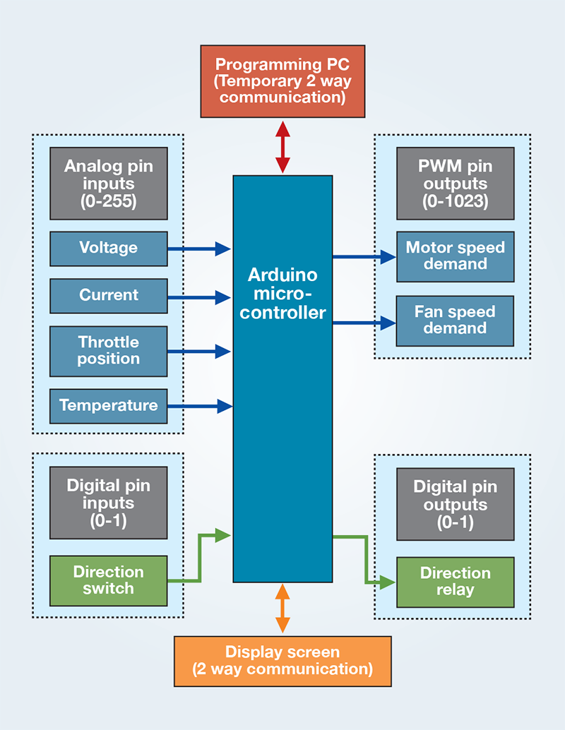
Computer controller inputs and outputs
With everything assembled on the bench the electronic inputs can then be processed onboard using user-written software. Arduino can also communicate with various other equipment, such as touch screens, using a range of standard formats which, while potentially daunting to the uninitiated at first, are fairly simple, and there are numerous examples online.
All software simply takes inputs, conducts operations on them, and uses that information to generate outputs. It must be very reliable, and that is another reason for using an Arduino rather than a more complex computer – Arduinos are extremely robust and any computer errors are unlikely to remain hidden.
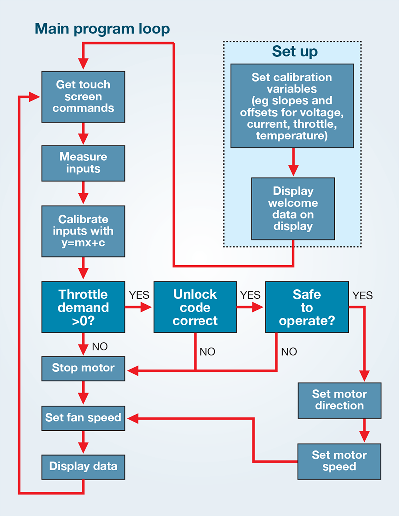
Suggested flow diagram for control software
Low cost computer control
The Arduino is a series of microcomputers originally produced in Italy by the Arduino company. As a not-for-profit organisation Arduino made the computer open-source, and thus versions of the smallest model, the Arduino Nano that I used, can be bought for £3-£5 each.
Programming is via a very simple language which can be freely downloaded onto a PC. The program is loaded into the Arduino via a USB cable.
Arduinos are ideal for control and monitoring as they are low cost, low power consumers, with a huge community of users, meaning a vast quantity of advice is freely available online.
Part 2: Computer control, monitoring, enclosure and cooling system – as published in the January 2019 issue of PBO.