
David Berry's complete boat electronics repair guide covers all the basics: the tools you need, tips and tricks plus step by step examples for fixing a broken NASA Clipper wind instrument, an Autohelm ST4000 and Garmin GPS 152

If you can solder it’s always worth taking things apart and having a go at repairing them as a last resort before paying for a replacement. In this boat electronics repair guide I will demonstrate how sometimes all you have to do is look closely, then wiggle every connector you can find to bring an electronic instrument back to life!
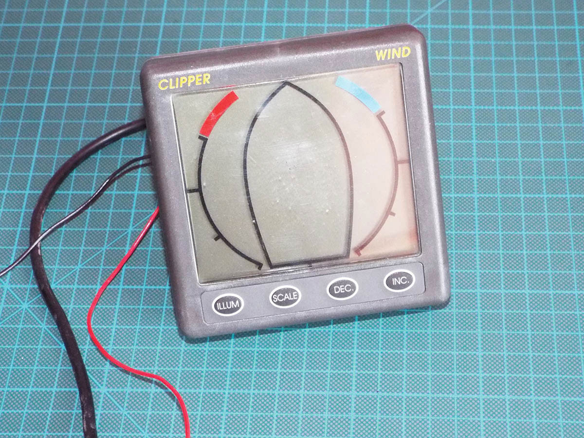
For example: this season the wind direction from my NASA Clipper Wind instrument was way off and the wind speed didn’t work at all. I climbed the mast and replaced the vane and cups to no avail, so it was time to get assertive.
14 boat electronics repair tips and tricks for boat owners
In this case a new instrument would set me back about £250, while the sum total of the components I was going to replace came to less than £10.
So in this article I’m going to show you how to replace all possible failed parts. I’m not going to talk about identifying the failed components – unless you have an oscilloscope, you can’t do it.
This approach may solve your problem and it may not, but risking £10 to save £250 seems like a good idea to me.
How I fixed an Autohelm ST4000 and Garmin GPS 152
How to fix any brand of wind instrument
1. Wiggle all the connectors inside and outside the unit.
2. If you have a meter, check individual units are receiving power.
3. If the system works when you connect the masthead unit to the display outside of boat, you have a wiring problem.
4. Find the active components. These will be transistors, which have three legs, or DIL devices which are rectangular. Identify them from the legend printed on the top and buy replacements.
5. Find the sensors. These will probably be like Hall effect devices described here, with three or four legs. Swap in replacements.
Which boat electronics repair tools should I use?
A few bits of kit and some background reading is recommended for newcomers to electronic surgery:
Note: We may earn a commission when you buy through links on our site, at no extra cost to you. This doesn’t affect our editorial independence.
Which 12V adapter power source?
If you can’t find one of these lurking around your house, I recommend the ALSISK AC 100-240V to DC 12V 1A(1000mA) 12W. It’s ideal since it comes with a screw terminal.
To identify whether any particular power supply is 12V, you need to look for the label then the ‘Output’.
Although I’ve talked about 12V throughout this article, 12V to 14V will be fine (your alternator puts out about 14.5V on your boat). Any current (A) value above 0.5 will be fine (equivalent to 6W).
How to stay grounded
I used an Aituo anti-static metal adjustable grounding wrist strap which prevents build up of static electricity with possible consequential damage to sensitive boat electronics.
Which soldering irons and solder
If you are going to buy a soldering iron, the best type for electronic work is a small-tipped iron with temperature control.
· Handskit 60W soldering kit includes solder wire, multimeter and more
· Amtech S1751 lead-free solder (it has flux inside the solder wire).

DIY electric outboard motor: How to build your own electric engine
Olly Epsom explains how (and why!) he built his own 1kW electric outboard motor for under £600

DIY at home: 100+ things to do and make in the workshop at home
In normal times we cover a lot of ground every month in Practical Boat Owner – online and in the…
What is inside a NASA Clipper Wind?
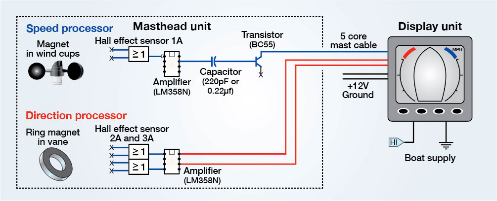
A rough pictorial scheme of the NASA Clipper Wind (not a circuit diagram)
The NASA Clipper Wind Version I (now superseded by V2) comprises a masthead unit and a display, which are connected by a five-core cable. This is a very simple design and other manufacturers may use variations on this basic scheme.
Buy Clipper Wind Version 2 from Mazzeonautica on Amazon
Most of the processing of wind speed and direction is done within the display unit, which takes signals from the masthead unit.
Within the masthead unit there are two pre-processor circuit boards: one is for wind speed and the other for direction.
The speed unit utilises a magnet in the rotating wind cup assembly. The faster the cups spin, the more often the magnet passes over the Hall effect sensor, which generates a pulse.
The direction indicator is a ring magnet that passes over two sensors in the masthead direction board. These sensors send analogue signals to the display along two of the cable cores. The position of the vane alters the voltages of the signals from the sensors, which enables the display to calculate where the vane is pointing.
In the speed unit pre-processing board I replaced the transistor, the amplifier and the capacitor. I assumed the Hall effect sensor would be OK because it is essentially a solid-state lump. However, if the fix had not worked, I would have replaced it as well.
The amplifier acts as a comparator which remains ‘off’ until a threshold value is exceeded then turns ‘on’ and so sharpens up the pulse.
The transistor acts as a ‘line driver’ providing enough power to overcome the resistance of the long cable from the masthead to the back of the instrument.
The capacitor connects the two active devices (amplifier and transistor) together. So the signal the display unit receives is a pulse every time the magnet in the windcup assembly passes over the sensor – the display unit then inverts the time between pulses to produce wind speed.
On the direction pre-processing board, I only replaced the amplifier.
Replacement boat electronics parts I ordered
• Both amplifiers (speed and direction) are LM 358 N (the ‘N’ is important)
• The magnetic sensors are Ratiometric Hall effect sensors type 503
• The single transistor is BC550C (NPN medium power type)
Step 1: Connecting for testing
The slim red and black power supply cores of the NASA Clipper display unit will need to be attached to a 12V-14V power supply (scroll down for the full buyer’s guide).
The thicker black cable contains the five wires that send power and receive signals to and from the masthead unit. I didn’t want to remove my entire connector cable from the boat, so I cut mine at the top of the mast and pulled the plug at the back of the display unit, then substituted some multi-core telephone wire for testing in the workshop.
I later reattached the masthead unit with a waterproof ‘chocolate block’ arrangement.
Step 2: opening up the display

The five-core cable (thicker black cable in previous step) terminates in a plug on the back of the display unit. It’s not obvious which plug pin connects to which core, so it’s easier to connect the temporary cables (the multicore telephone wire) to the display by dismantling it.
Once you have unscrewed the display and separated the halves, you need to attach five wires which will join the masthead unit to the display.
All you have to do is connect the red in the display to the red in the head unit, followed by blue to blue and so on. The easiest way to do this is by soldering the wires to the terminal pads on the boards while leaving the original wires in place.
3. Opening the masthead unit

The first step with the masthead unit is to remove the vane and cups then unscrew the seven screws holding the unit together. At the end of the arm is a gland and you need to slacken the nut to allow the cable which contains the five cores to be drawn into the body of the unit so that the circuit boards can be removed.
4. Extract the processor boards
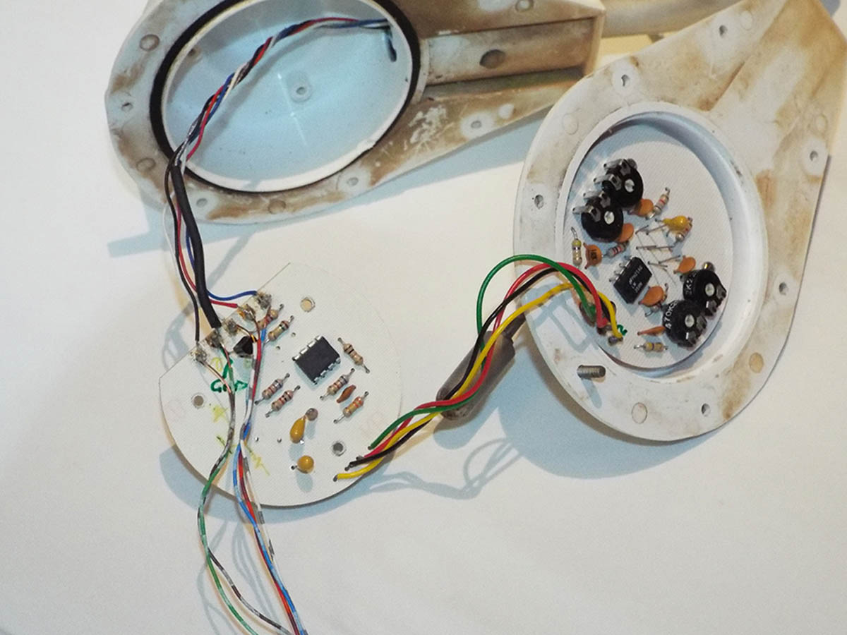
Remove the three self-tapping screws holding the speed processor board into the plastic housing. At the bottom left of the photo are the wires I’ve substituted to connect the masthead unit to the display. The original wires at the top of the picture will later be reconnected to the wire in the mast. The ones to the right connect to the direction processor.
Boat electronics repair #1: Fixing NASA Clipper Wind anemometer
5. Identifying the components
 In my unit, the speed data was not being displayed at all, so one of the three processing components (labelled) was faulty. To save time, I decided to simply replace them all. The capacitor may not always look like this one but it will be in this position.
5a. Get a close-up view
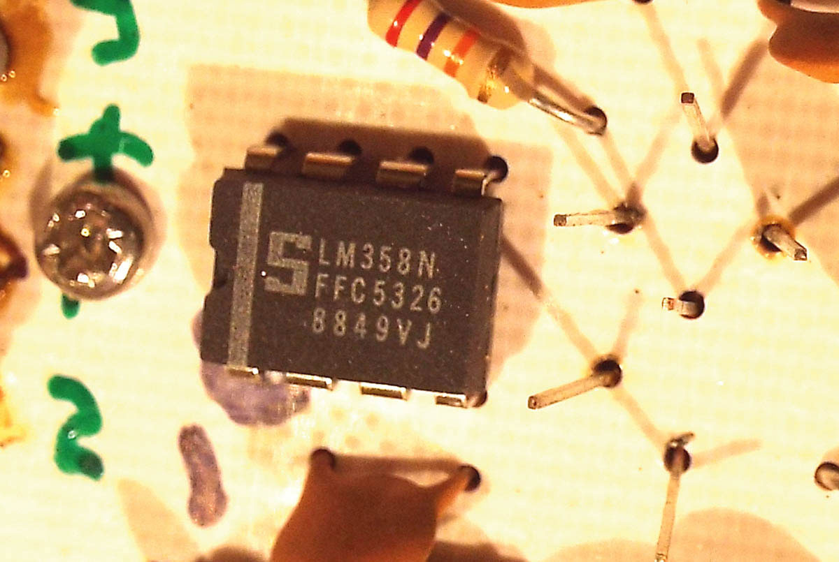
It’s worth stating here that all electronic components are identified with their type number printed on them. You’ll probably need a lens to see the numbers properly though. For example, the rectangular component here is an ‘LM358N’. The transistor will be marked ‘BC55’ and the capacitor ‘220pF’.
6. Removing components from circuit board

It doesn’t really matter how you remove the three components, provided you can do so without damaging or bridging the copper tracks on the board. They are soldered on the reverse of the board, so turn it over and melt the solder. I use this thing called a solder sucker, which is like a spring-loaded syringe, but if you simply cut through the legs of the transistor, amplifier and capacitor then remove the left-over bits of wire with tweezers while the solder is molten, that’s fine.
You need to end up with a hole into which the new component’s legs will fit, and that may mean wiping away the solder with the tip of the iron if you need to.
7. Identifying the solder joints

This image shows the solder pads that relate to each of the components that need replacing. The red ones are the LM358N amplifier, the blue ones are the capacitor and the green, the transistor. When removing the old components and cleaning up the holes with the soldering iron be careful not to bridge between two holes or tracks with solder.
8. Fitting the new components

To fit the three new components into the holes you have made, turn the board over and solder each of their legs into place then snip off any spare wire. If you’re new to soldering, the way to proceed is to heat the junction of the wire leg of the component with the track on the board then add solder. The only danger is overheating the track, which may result in it delaminating, so be cautious until you’ve developed the necessary skill.
Don’t forget to ground yourself with your wrist strap.
9. Capacitor in detail
 This particular new capacitor is much larger than the one it replaces but as long as its capacitance value (220pF) is the same then it will work. The physical size of the ‘can’ doesn’t matter.
It’s always worth marking the board with a felt tip pen so that you know which way around the components have to go and which colour wire is connected where. Here the number ‘1’ refers to the first pin of the amplifier (the amplifier has a scallop one end and pin 1 is that end and on the left, viewed from above) and the reversed ‘D’ represents the shape of the transistor seen from above.
The capacitor can be mounted either way.
10. Hall effect sensors

This is the magnetic Hall effect sensor on the reverse side of the speed board. If all else fails, you could try replacing this but make sure you get it the right way round. The plastic case is shaped and the wire legs must be orientated as shown here.
Boat electronics repair #2: Fixing NASA Clipper Wind direction sensor
1. Sensors and amplifiers
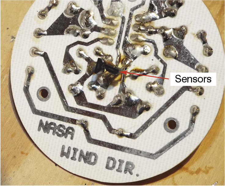
I decided that since I had the thing in bits, I may as well change the sensors and amplifier on the direction board too. So I took the board out by removing the three screws but left the wires connected. I replaced the sensors one at a time (so that I could position them at the right height to detect the magnet).
The orientation is important so draw their profiles onto the board.
This is not a great photo – the two sensors are at the centre of the shot and at this point I hadn’t drawn their outlines.
2. Close-up of a Hall Effect magnetic sensor

The Hall effect magnetic sensors: Don’t be afraid to bend the wire legs carefully until they are the right shape to fit the holes they go in.
Ensuring correct orientation is vital. To work, they must be fitted the same way around as the ones you remove and at the same height above the board.
The sensors are chamfered to enable correct orientation.
3. Replacing the amplifier chip
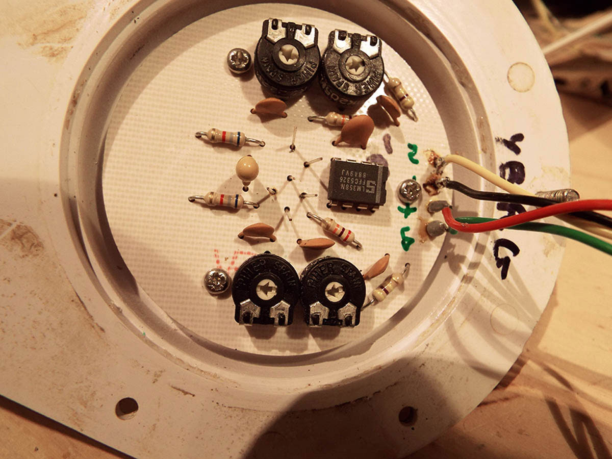
While I was at it, I replaced the amplifier chip. Again I marked the board with the orientation before I removed the old one. It’s worth saying that the worst part of this operation was trimming each of the potentiometers (the four black round devices) to get the unit trimmed up again. The pots seem to trim each of the four directions and are very sensitive – tweaking one upset the others.
So, although for me it was worthwhile changing the amplifier and sensor’s components because my instrument was not giving a reliable direction display, if your direction indicator is functioning properly leave it well alone! If you do have to change the components, it’s worth photographing the position of the pots (that is the small white arrowed centres) before you begin so that you can always go back to the start position.
4. Connecting the amplifier’s legs

This is the solder side of the direction board and the red dots show the legs of the amplifier’s solder pads.
Conclusion: testing the boat electronics repairs
So did it work? Yes it did. To test the speed function wave a magnet close to the sensor and watch the display. Since the windvane has a circular magnet embedded in it, the only way to test the direction function is to replace the direction board in the housing and rotate the vane slowly. After that, unsolder the wires you added to link the display to the masthead unit and check the original wires are still in place. Then screw it all back together.
Well done, you’ve made a successful repair!
Why not subscribe today?
This feature appeared in the September 2020 edition of Practical Boat Owner. For more articles like this, including DIY, money-saving advice, great boat projects, expert tips and ways to improve your boat’s performance, take out a magazine subscription to Britain’s best-selling boating magazine.
Subscribe, or make a gift for someone else, and you’ll always save at least 30% compared to newsstand prices.
See the latest PBO subscription deals on magazinesdirect.com