
Brian Robertson on the challenges of DIY boat engine replacement and why he chose a Beta 30 over the Volvo Penta D1-30

I bought my 1987 Moody 31 MkII in September 2017 and still remember the excitement of flying down with a friend from Edinburgh to Southampton for the day to view her.
Tidecatcher, or TC as she is now affectionately known, was well appointed and, for her age, in generally good condition. The Volvo Penta 2003 engine, although original (yes Volvo launched its 2000 series in the 1980s), seemed to run well under test and, as an added bonus, it came with a one year warranty.
And sure enough, the 30-year-old engine served me well, including, in my first season as owner, a 740-mile return trip through the Caledonian Canal to the west coast of Scotland from my home berth at the Royal Forth Yacht Club in Edinburgh.
However, to reduce the likelihood of having to deal with increased regular, ongoing and potentially costly attention, with always the risk of complete failure, and knowing that I also wish to keep this boat for several years, I decided to renew the engine.
Which marine engine?
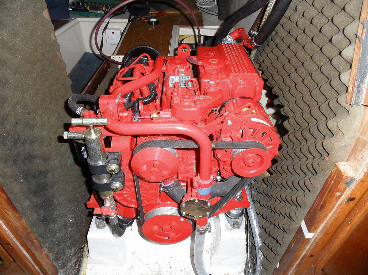
For long term reliability Brian decided to replace his boat’s old Volvo Penta 2003 motor with this new Beta 30
You’d assume that the natural replacement for the 28hp Volvo Penta 2003 would be the D1-30, but there are alternatives. I’d previously owned a boat with a Beta engine, so I was also focussed on a Beta 30.
But did it need to be such a powerful unit? The old rule of thumb was to calculate 3hp per tonne, and I believe the generally held view now is that it should be 4hp per tonne. The Moody 31 MkII blurb confirms that the waterline length of the boat is 7.75m and the displacement is 4.5 tonnes so, on that basis, you could argue perhaps that a 20hp engine would be sufficient.
But I was always impressed by the fact that the Moody 31 MkII came with a 28hp engine by design, and I wasn’t really wishing to diminish that by much.
So although the slightly smaller Beta 25 would seem to be a sensible option, Beta rather cleverly offers ‘Volvo Penta 2003 engine feet’ to suit their Beta 30 engine.
Additionally, Beta offer a TMC 60 A gearbox option, with a 7° down angle, specifically to match the similar down angle on the MS2B gearbox fitted as standard to the VP 2003 power units installed in the Moody 31.
So, as this is something which Beta has obviously put some thought into, it would appear that the Beta 30 is a natural replacement for many yachts currently installed with the VP 2003 power unit, and specifically Moody 31s.
Armed with this knowledge I made contact with Beta head office to seek further information on their Beta engine range. The price difference between the Volvo Penta D1-30 and Beta 30 power units was negligible, but Beta’s self-servicing warranty was attractive, as was the additional Southampton Boat Show discount which they were offering.
I decided to go with Beta and ordered the shallow sump option with VP 2003 engine feet and the 7° down angle gearbox. The Beta 30 engine happens to rotate in the opposite direction to the VP2003 power unit, so I also had to factor in the cost of a new propeller.
Mad about Moody 31
Moody 31 specifications
I remember being smitten when I was first shown an image of this particular make of yacht and I think Bill Dixon really hit the sweet spot when he came up with this general design which, of course, he replicated across other models of the Moody range in the 1980s and 1990s.
Tidecatcher came with a full Raymarine electronics package and an extensive maintenance record going back many years which detailed, in particular, the recent (2014) replacement of the keel bolts and also the spline conversion for the MS2B gearbox.
It was comforting to know that these two Achilles heel issues had already been addressed!
SPECIFICATIONS
LOA: 9.37m (30ft 7in)
LWL: 7.75m (25ft 4in)
Beam: 3.2m (10ft 4in)
Draught: 1.12m (3ft 6in)
Displacement: 4,530kg (9,986lb)
Ballast: 1,667kg (3,675lb)
Ballast ratio: 36.8%
Sail area: 51.84sq m (558sq ft
Sail area/displacement ratio: 19.3
Diesel: 90.9lt (20gal)
Water: 136.3lt (30gal)
www.moodyowners.org

Removing the Volvo Penta 2003 engine
There was a six-week lead time for delivery of the new engine, so that gave me the chance to set about removing the old VP 2003.
I first of all disconnected the prop shaft and removed the clamp coupling from the gearbox flange.
I then decided to remove the PSS (Packless Sealing System) shaft seal assembly and install a home-made split mandrel to hold the shaft absolutely central in the stern tube – I used my workshop lathe to turn the mandrel from a piece of aluminium bar. This is critical for aligning the new engine.
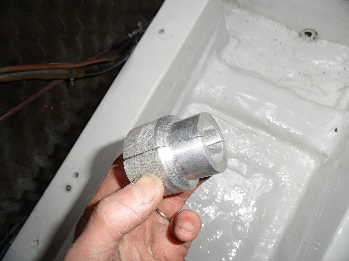
1. An aluminium split mandrel was turned on the lathe to hold the prop shaft centrally in the stern tube once the Packless Sealing System had been removed.
2. The home-made mandrel holds the shaft dead-centre in the stern tube so the new engine can be perfectly aligned during installation.
Having disconnected the shaft, fuel lines and electrical cables, removing the engine from this position is almost a direct vertical lift out through the hatch.
I labelled all the disconnected wires to make connecting the new engine easier.
But in order to work on the engine bearers, I first needed to pull the old engine forward into the cabin, so I rigged a timber beam across the hatch opening from which I suspended a strong but lightweight lifting pulley arrangement. Having lifted the engine off the bearers I simply slid a plank in beneath the engine sump and then dragged it into the cabin.

3. The old Volvo Penta 2003 has been lifted out and now the new Beta 30 is carefully lowered down into Tidecatcher’s cabin.
The photo (above) shows a hydraulic lorry loader lowering the new engine into the cabin – the old one was hauled out earlier in the same visit by the crane.
Improving engine bay access
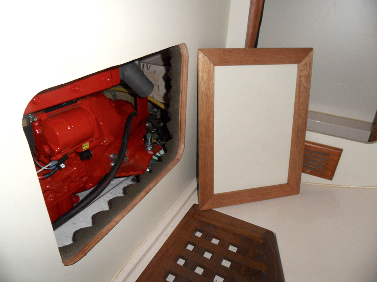
4. A hatch was created in the heads compartment to give portside access to the engine mounts and starter motor electrics.
As all Moody 31 owners will know, access to the engine compartment is already fairly generous but when the cabin steps are removed along with the cross supporting bar and the ‘box’ storage unit in the aft cabin, access is even better and perfectly adequate for most of what needs doing in general maintenance.
Having said that, I was greatly impressed by an image I viewed recently of a Moody 31 which had an access hatch installed to the engine compartment from the heads.
This struck me at the time as a very sensible and useful modification and so I decided to replicate it on Tidecatcher.
As the image shows, this hatch gives greatly improved portside access to the engine mountings as well as the starter motor electrics.
Modifying marine engine bearers

5. Only two new holes needed to be drilled into the engine bearers to accommodate the new mounts. Once drilled these were tapped to M10 thread size.
With the old engine out of the way I set about making preparations for the new power unit. The Beta technical information confirmed that, of the eight existing drilled engine-bearer holes, six are suitably positioned to match the Beta 30 mountings (with the suitably installed VP 2003 engine feet).
That meant that only two holes had to be drilled and tapped for the new engine to sit on top of the existing engine bearers.
The M31 engine bearers are encased in fibreglass, but beneath a top layer of fibreglass there’s a steel plate to which the engine mounting bolts are secured. The thread size is M10 and, having carefully taken my measurements, I drilled and tapped the two holes as directed.
Fitting the new Beta 30 marine engine
With the new engine in the cabin, I again rigged up the lift pulley arrangement and started manoeuvring it into place. The Beta 30 power unit is 20kg lighter than the VP2003 power unit, so I found it slightly easier to push around!
The first challenge was the engine mountings and feet.
I’d loosely mounted the four flexible mountings on the engine bearers, bolting them to the appropriate threaded holes, but I noticed that when I lowered the engine onto the mounting spindles the front and rear spindles were being pushed very slightly apart.
Despite knowing that the VP2003 engine feet had been designed specifically for the Moody 31 engine bearers, I decided to modify the rear flexible mounting plates to allow them to sit slightly further apart from the front ones (5mm was enough) and I was then able to lower the engine onto the mountings with no visible signs of stress.
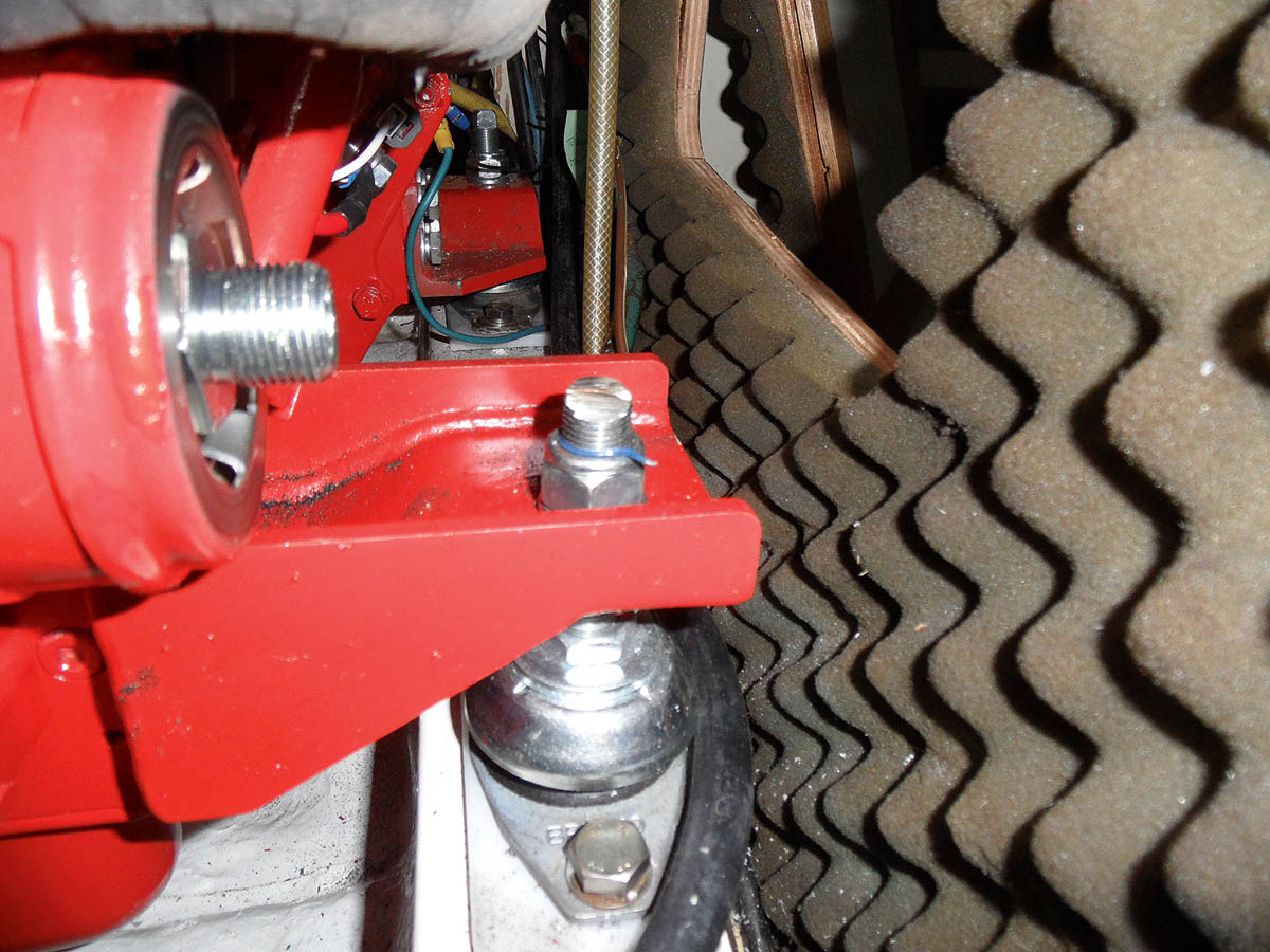
6. The portside engine mount spindle had to be sawn off slightly shorter in order to clear the spin-on engine oil filter (removed for access to the spindle in this photo).
One other mounting issue concerned the front portside mounting spindle which sits so close to the engine oil filter that, once the engine has been lowered onto the mountings, it is impossible to get the top securing nut onto the mounting spindle with the filter in place.
I had no option but to remove the filter and then cut off the top third or so of the spindle with an angle grinder. I didn’t like interfering with the mounting in this way but the oil filter has to be easily accessible.
Continuing with the installation, I had positioned the prop-shaft clamp coupling (minus the ‘flexi’ component) on the end of the prop shaft and nipped up the locking bolts.
I was pleased to see that the gearbox flange had faced up to the clamp coupling flange well and was sitting about 15mm lower than it. As the engine mountings were at their lowest position this variance was perfectly acceptable as there was plenty of scope for adjustment.

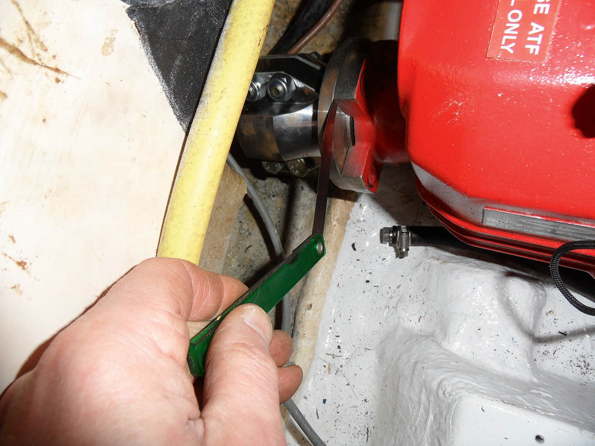
7. A set of engine mount spacers were cut from 7mm-thick polythene which is easily worked, almost indestructibly tough and won’t rust.
The Beta technical information recommends that the engine feet should be positioned as low as possible on the flexible mounting spindles, so I decided to make up some simple spacers to sit between the flexible mounting plates and the engine bearers to achieve this.
These spacers are usually made of steel but I used 7mm thick sheet polythene, which is extremely dense, completely impervious to oil and diesel, and almost indestructible.
With these spacers in place it meant that I was only going to have to raise the engine up the threaded spindles a few millimetres in order to get the gearbox and prop shaft flanges to mate correctly.
How to align a propeller shaft
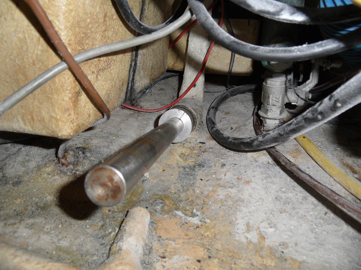
8. By careful adjustment of the engine mounting spindles and precise feeler gauge measurement of the gaps between gearbox and prop shaft flanges at north, south east and west, perfect alignment can be achieved.
Prop shaft alignment will always be one of the most critical aspects of any engine installation and even a slight misalignment will cause vibration and possibly wear on other components.
Many manuals will recommend the use of a dial gauge to confirm alignment accuracy and I certainly wouldn’t argue against this. However, if the feeler gauge measurements are achieved as described below then the installation should be accurately aligned.
My shaft mandrel was holding the shaft central through the cutless bearing and stern tube, meaning the prop shaft flange was perfectly positioned. Now I had to adjust my engine mountings to get the gearbox flange to match the propshaft flange perfectly.
Once my spacers were in place I raised the engine feet up the mounting spindles about 6mm or so and then pulled the shaft flange forward to get it to mate into the machined grooves on the gearbox flange.
After some adjustment I did manage to get the two flanges to mate fairly easily, but in order to ensure perfect alignment I opted to use feeler gauges at the north, south, east and west points of the flanges. By careful adjustment of the mountings I was able to get the four measurements spot on and, having done this, I then tightened up the engine mountings and repeated the measurement, as tightening can sometimes alter the position of the engine!
Installing a marine exhaust anti-syphon valve

9. Rubber hose and copper tubing connect the exhaust manifolds to an anti-syphon valve fitted at least 300mm above on a bulkhead (inset below).
To avoid the risk of sea water coming back into the engine through the water cooling circuit, the exhaust manifold at the rear of the engine (into which the raw cooling water discharges) should be a minimum of 300mm above the boat’s waterline.

Antisyphon installation
Although Moody didn’t install anti-syphon valves as standard, I calculated the manifold on my VP2003 to be only marginally above the boat’s waterline. So I installed an anti-syphon valve in the seawater inlet circuit using 18mm copper tube and rubber hose.
While a suitably positioned anti-syphon valve will protect an engine from water ingress from the inlet side, exhaust water ingress should be prevented by having a suitable fall into the exhaust water trap, along with a sufficient loop in the exhaust pipe before discharging through the hull. Beta guidelines state that this fall into the water trap should be a minimum of 300mm.
The standard water trap on the Moody 31 is beneath the cockpit locker floor, which keeps it well out of the way, yet still easily accessible. But I had two concerns: the fall from the exhaust manifold to the water trap inlet was less than 300mm, and there was a dip in the pipe, which was clearly going to hold water when the engine was switched off.

10. The water trap was moved to a new position nearer to the engine to allow a minimum 300mm fall from the exhaust manifold.
So I decided to move the water trap into the small compartment in the aft cabin, nearer the engine and close to the stern tube. I had to alter the angle of the inlet to the stainless steel water trap, which required some welding, but for those without welding skills or equipment, most engineering workshops would regard this as a simple and inexpensive task.
I fibreglassed a couple of hardwood bearers to the inner hull for the water trap to sit on and I mounted the base of the trap on rubber packers to give it a bit of flexibility to allow for engine vibration.
I was then able to connect the engine exhaust to the water trap with a short length of 50mm flexible exhaust hose and I joined the two sections of hose beneath the cockpit locker (where the water trap used to be) with a short piece of stainless tube (easily purchased on the internet).
Re-routing diesel fuel lines
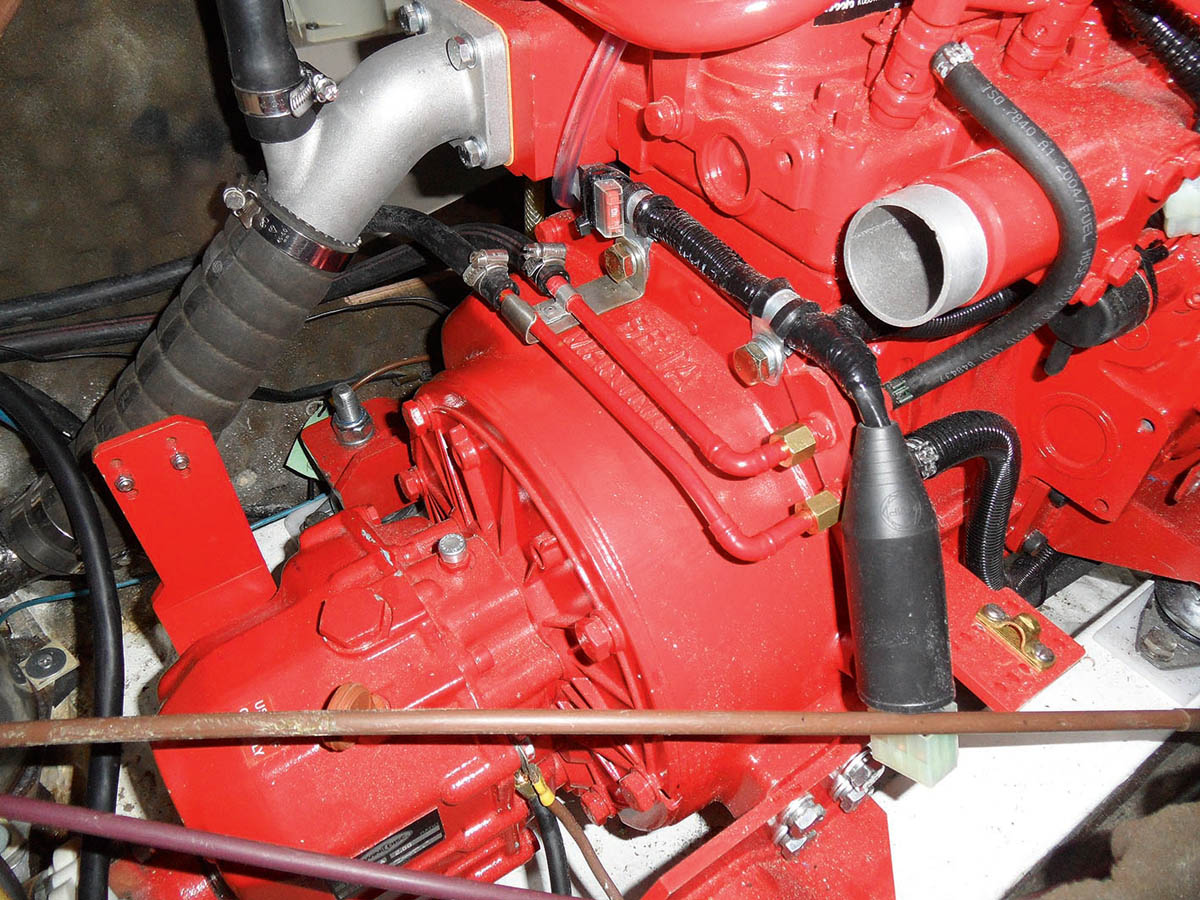
12. New diesel feed and return fuel lines were made up from 8mm copper pipework to run from the compression connections on the starboard side of the engine to the existing pipework on the port side. Pipes were secured by a bracket on the bell housing.
Both the diesel engine feed and return connections (8mm compression) are positioned conveniently at the rear of the engine, near the top of the bell housing, and 8mm copper pipework can be laid easily to and from these points.
I made up a simple bracket to support these pipes as I led them to the existing diesel feed and return pipes on the port side of the engine compartment.
Reconnecting marine diesel electrics

13. The Beta Marine engine control panel was conveniently almost the same size as the previous Volvo one, so fitted neatly into the aperture in the cockpit without major modification.
The Beta ABV control panel, which rather conveniently is almost exactly the same size as the Volvo Penta one, fitted neatly into the cockpit aperture and the harness was laid through the bulkhead into the engine compartment. This then just left a simple multi-plug connection to the engine wiring harness.
The earth wires (and there were a few of them) were reconnected to appropriate engine bolts and the engine ‘live’ and ‘earth’ were connected to the starter motor.
Choosing the right propeller
As mentioned earlier, the Beta engine rotates in the opposite direction to the Volvo Penta so I ordered a new propeller through Beta’s recommended prop design and supply service.
How to choose the right propeller for your boat
My existing prop was 16in diameter but, to prevent ‘tip noise’ it is recommended to leave a gap between the prop tip and the hull of at least 10% of the prop’s diameter.
My gap was too small and I had experienced this noise on a few previous occasions when motoring. The first time I heard it I thought I’d run a bearing in the gearbox!
To give me sufficient hull clearance, my new propeller had to be no larger than 15in diameter and this was manufactured to suit my existing shaft taper.
Finishing off
With the raw water inlet pipe connected at the front of the engine and a general tidy up of wires and cables etc, all that was left to do was to refit the PSS shaft seal and prepare the engine for trial.
Conclusion

The shiny new Beta 30 installation in Tidecatcher. Access to main service items is good and Brian is very pleased with the result.
Having never attempted anything like this before I must confess to an air of profound satisfaction upon the successful installation of the engine.
Of course it is useful to have some engineering aptitude, access to a welding set, drills/taps/dies and a friend with a hydraulic lorry loader! But even without these advantages, if you prepare carefully, plan each step and give yourself plenty of time, it is doable and may prove extremely worthwhile.
Putting aside the considerable financial saving on being able to complete this project myself, the main benefit is the additional technical knowledge I now have on my own engine. This is very likely to pay dividends in the future.