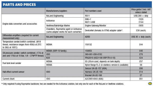
Andy Johnson converts engine, transmission and electrical system data to NMEA2000 and displays the numbers on his Moody 31 chartplotter.
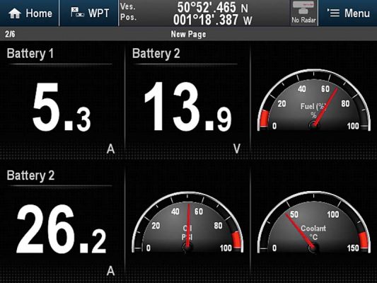
Modern chart plotters and marine instruments, in addition to displaying the chart, radar and many other functions, also offer a comprehensive set of data pages to display information for one or more engines, transmissions and electrical systems. Here, we take a Moody 31 and its Volvo Penta 2003 engine and add a host of engine and electrical data to display via the NMEA2000 network.
Three stages of conversion are involved, beginning with the sensors themselves – referred to as senders – which will convert the parameter being measured into an electrical signal. The second and third stages, accomplished by the data converter unit, are to convert the electrical signal into a digital number (digitisation) and arrange it into a format suitable for transmission onto the NMEA2000 network. Some larger engines use the automotive J1939 network, which would then have to be converted into the NMEA2000 format to display on the chart plotter.
The difference between resistive senders and pulse senders
The most common senders are resistive, such that their resistance changes with the parameter being measured, or pulse-type senders where the frequency of the pulses changes with the speed being monitored. The coolant temperature, oil pressure and fuel level senders used here are all resistive. Measuring current is achieved using either a resistive device called a current shunt or a Hall effect sensor (which measures current in a different way). The alternator itself provides the pulse output for engine revs so no additional sender is required.
The temperature and pressure senders need to fit in the same locations as the original senders, so they need the correct thread. The temperature sender should measure from about 25°C to above the alarm point (95°C). The oil pressure sender must cope with the highest possible pressure for a cold engine at start-up (7 Bar, 100psi in this case).
There are many tank level senders on the market: the one chosen was a simple tube type, changing the resistance in small steps as the float moves up and down. Once the flange is fitted, the actual sender simply screws in – providing there is enough height above the tank to poke it through (check this first!).
Measuring current presents more of a challenge. It would be useful to display total charging current and current consumption from the domestic batteries. Current can be measured by a ‘resistive current shunt’, which has a very small fixed value of resistance, creating a voltage across its terminals proportional to the current flowing through them (remember Ohm’s Law?). Alternatively, a Hall effect sensor measures the magnetic field generated by the flow of current in the cable (passing through its aperture), producing a small voltage proportional to it. This type of sensor also needs a 12V supply. Both are 60A rated, as they would be damaged if subjected to prolonged currents greater than their rating. They give 1mV/A output, and this is increased by the use of differential amplifiers to multiply this very small signal by 50, increasing it to 50mV/A.
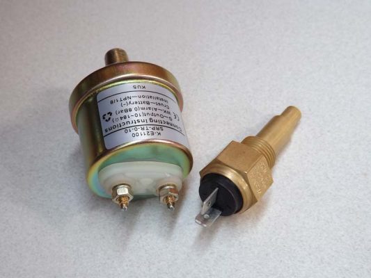
Oil pressure and coolant temperature senders with integral alarm switches.
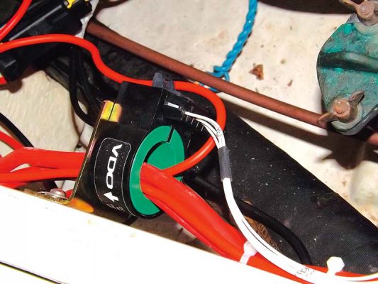
Cables from the alternator and other sources of charging are passed through the Hall effect sensor aperture.
Measuring battery voltage only requires a wire from the battery terminal to the data converter channel input, or is measured internally on some units.
To minimise electrical interference, a new 0V bus was installed for all the instrumentation, connected directly back to the domestic battery negative terminal and screened multi-core cable
was used for the sender signal connections.
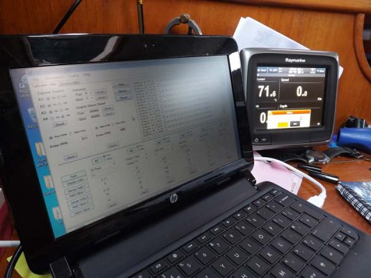
The data converter itself is an electronic unit with configurable input channels, taking in the signals from the resistive and pulse-type sensors. The resultant numbers, representing the values of the parameters being measured, are then assembled into the correct format and sent to the display via the NMEA2000 data network.
Data converters either piggyback off existing sensors and instruments, picking up the sensor outputs at their terminals, or new sensors are fitted and wired to the data converter inputs, or a mixture of both.
Tried and tested
Click through to the next page (scroll down) to see a detailed description of the first of the three units that we used for this installation (the other two are on subsequent pages). All three data converters work well. The advantage with the NoLand RS11 is its flexibility (allowing current to be measured) at the expense of a slightly more complex set-up. For a more standard installation, without current measurement, then the Actisense EMU-1 is very simple to configure. The Veethree EGM is perfect for vessels with larger engines (or outboards) which have their instruments on the J1939 network, an approach becoming more common in the marine sector.